
RAM 2500 Truck 2WD L6-5.9L DSL Turbo VIN C (2002)
Remote Control: Description and Operation
REMOTE SWITCHES
A remote radio switch option is available on models equipped with the AM/FM/CD/cassette/3-band graphic equalizer (RAZ sales code) radio receiver
and the high-line Central Timer Module (CTM). Refer to Electrical, Body Control/Central Timer Module for more information on this component.
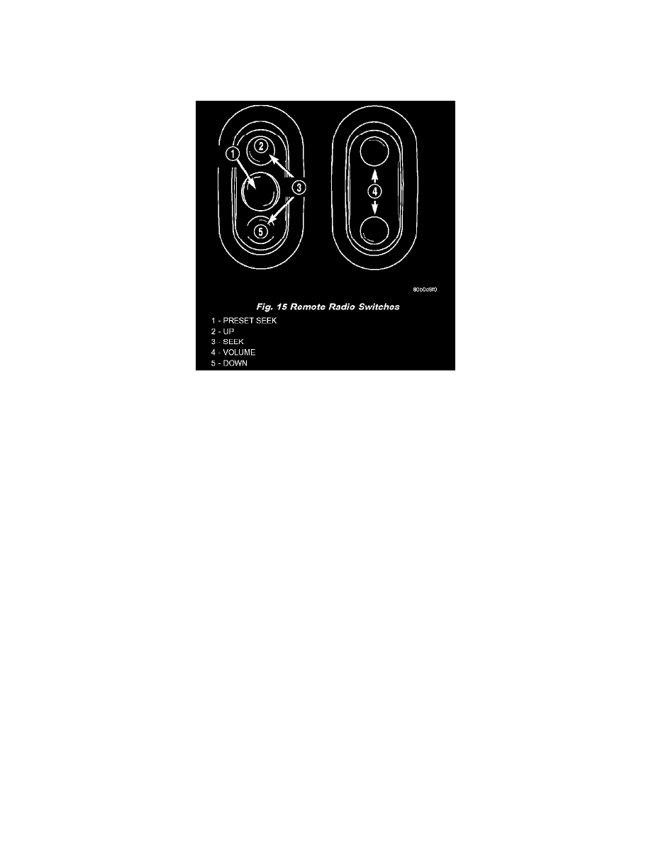
Fig. 15 Remote Radio Switches
Two rocker-type switches are mounted in the sides of the rear (instrument panel side) steering wheel trim cover. The switch ON the left side is the seek
switch and has seek up, seek down, and preset station advance functions. The switch ON the right side is the volume control switch and has volume up,
and volume down functions. The two switches are retained in mounting holes located on each side of the rear steering wheel trim cover by four latches
that are integral to the switches.
The remote radio switches share a common steering wheel wire harness with the vehicle speed control switches. The steering wheel wire harness is
connected to the instrument panel wire harness through the clockspring. Refer to Electrical, Clockspring for more information on this component.
The remote radio switches are resistor multiplexed units that are hard wired to the high-line or premium CTM through the clockspring. The CTM
monitors the status of the remote radio switches and sends the proper switch status messages on the Chrysler Collision Detection (CCD) data bus
network to the radio receiver. The electronic circuitry within the radio is programmed to respond to these remote radio switch status messages by
adjusting the radio settings as requested.
For diagnosis of the CTM or the CCD data bus, the use of a DRB III scan tool and the proper Diagnostic Procedures are recommended. For more
information on the features and control functions for each of the remote radio switches, see the owner's manual in the vehicle glove box. For complete
circuit diagrams, refer to the appropriate wiring information. The wiring information includes wiring diagrams, proper wire and connector repair
procedures, details of wire harness routing and retention, connector pin-out information and location views for the various wire harness connectors,
splices and grounds.