
RAM 2500 Truck 2WD L6-5.9L DSL Turbo VIN C (2002)
Seat Heater Relay: Testing and Inspection
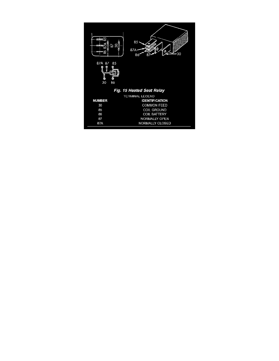
Fig. 15 Heated Seat Relay
The heated seat relay is located in the Junction Block (JB) on the left end of the instrument panel in the passenger compartment of the vehicle. Refer to
Wiring Diagrams for the location of complete heated seat system wiring diagrams.
WARNING: ON VEHICLES EQUIPPED WITH AIRBAGS, DISABLE THE AIRBAG SYSTEM BEFORE ATTEMPTING ANY STEERING
WHEEL, STEERING COLUMN, OR INSTRUMENT PANEL COMPONENT DIAGNOSIS OR SERVICE. DISCONNECT AND
ISOLATE THE BATTERY NEGATIVE (GROUND) CABLE, THEN WAIT TWO MINUTES FOR THE AIRBAG SYSTEM
CAPACITOR TO DISCHARGE BEFORE PERFORMING FURTHER DIAGNOSIS OR SERVICE. THIS IS THE ONLY SURE
WAY TO DISABLE THE AIRBAG SYSTEM. FAILURE TO TAKE THE PROPER PRECAUTIONS COULD RESULT IN
ACCIDENTAL AIRBAG DEPLOYMENT AND POSSIBLE PERSONAL INJURY.
Relay Test
1. Remove the heated seat relay from the JB. Refer to Heated Seat Relay for the location of the proper heated seat relay removal procedures See:
Service and Repair.
2. A relay in the de-energized position should have continuity between terminals 87A and 30, and no continuity between terminals 87 and 30.
If OK, go to Step 3.
If not OK, replace the faulty relay.
3. Resistance between terminals 85 and 86 (electromagnet) should be 75 ± 5 ohms.
If OK, go to Step 4.
If not OK, replace the faulty relay.
4. Connect a battery to terminals 85 and 86. There should now be continuity between terminals 30 and 87, and no continuity between terminals 87A
and 30.
If OK, perform the Relay Circuit Test that follows.
If not OK, replace the faulty relay
Relay Circuit Test
1. The relay common feed terminal cavity (30) is connected to battery voltage and should be hot at all times.
If OK, go to Step 2.
If not OK, repair the open circuit to the fused B(+) fuse in the Power Distribution Center (PDC) as required.
2. The relay normally closed terminal (87A) is connected to terminal 30 in the de-energized position, but is not used for this application. Go to Step
3.
3. The relay normally open terminal (87) is connected to the common feed terminal (30) in the energized position. This terminal supplies battery
voltage to the heated seat module. There should be continuity between the cavity for relay terminal 87 and the B(+) to heated seat module circuit
cavity of the heated seat module wire harness connector at all times.
If OK, go to Step 4.