
RAM 2500 Truck 2WD L6-5.9L DSL Turbo VIN C (2002)
Information Bus: Description and Operation
System Details
Following are additional details of each of the above system requirements.
Bus (+) And Bus (-) Circuits
The two wires (sometimes referred to as the "twisted pair") that comprise the CCD data bus are the D1 circuit [Bus (+)], and the D2 circuit [Bus (-)]. The
D in D1 and D2 identify these as diagnostic circuits. Transmission and receipt of binary messages on the CCD data bus is accomplished by cycling the
voltage differential between the Bus (+) and Bus (-) circuits.
The two data bus wires are twisted together in order to shield the wires from the effects of any Electro-Magnetic Interference (EMI) from switched
voltage sources. An induced EMI voltage can be generated in any wire by a nearby switched voltage or switched ground circuit. By twisting the data bus
wires together, the induced voltage spike (either up or down) affects both wires equally. Since both wires are affected equally, a voltage differential still
exists between the Bus (+) and Bus (-) circuits, and the data bus messages can still be broadcast or received. The correct specification for data bus wire
twisting is one turn for every 44.45 millimeters (1 3/4 inches) of wire.
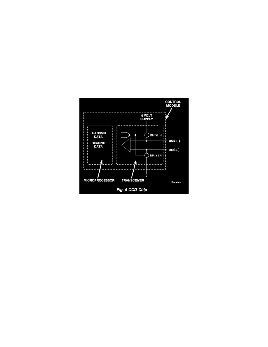
Fig. 5 CCD Chip
CCD Chips
In order for an electronic control module to communicate on the CCD data bus, it must have a CCD chip. The CCD chip contains a differential
transmitter/receiver (or transceiver), which is used to send and receive messages. Each module is wired in parallel to the data bus through its CCD chip.
The differential transceiver sends messages by using two current drivers: one current source driver, and one current sink driver. The current drivers are
matched and allow 0.006 ampere to flow through the data bus circuits. When the transceiver drivers are turned ON, the Bus (+) voltage increases
slightly and the Bus (-) voltage decreases slightly. By cycling the drivers ON and OFF the CCD chip causes the voltage on the data bus circuit to
fluctuate to reflect the message.
Once a message is broadcast over the CCD data bus, all electronic control modules on the data bus have the ability to receive it through their CCD chip.
Reception of CCD messages is also carried out by the transceiver in the CCD chip. The transceiver monitors the voltage on the data bus for any
fluctuations. When data bus voltage fluctuations are detected, they are interpreted by the transceiver as binary messages and sent to the electronic control
module's microprocessor.
Bus Bias And Termination
The voltage network used by the CCD data bus to transmit messages requires both bias and termination. At least one electronic control module on the
data bus must provide a voltage source for the CCD data bus network known as bus bias, and there must be at least one bus termination point for the data
bus circuit to be complete. However, while bias and termination are both required for data bus operation, they both do not have to be within the same
electronic control module. The CCD data bus is biased to approximately 2.5 volts. With each of the electronic control modules wired in parallel to the
data bus, all modules utilize the same bus bias. Therefore, based upon vehicle options, the data bus can accommodate two or twenty electronic control
modules without affecting bus voltage.