
RAM 2500 Truck 2WD L6-5.9L DSL Turbo VIN C (2002)
Electrical Accessory Panel: Description and Operation
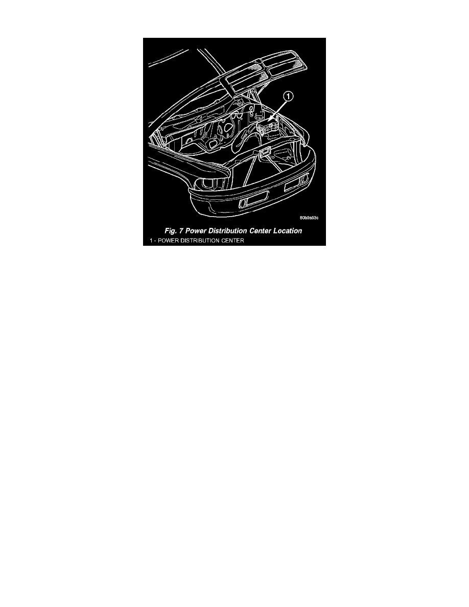
Fig. 7 Power Distribution Center Location
POWER DISTRIBUTION CENTER
All of the electrical current distributed throughout this vehicle is directed through the standard equipment Power Distribution Center (PDC) (Fig. 7).
The molded plastic PDC housing is located in the left front corner of the engine compartment, just behind the battery. The PDC houses the generator
cartridge fuse and up to twelve maxi-type cartridge fuses, which replace all in-line fusible links. The PDC also houses up to thirteen blade-type fuses
(two standard-type and eleven mini-type), up to seventeen International Standards Organization (ISO) relays (five standard-type and twelve
micro-type), two joint connectors (one eighteen-way and one twenty-eight-way), a forty-three-way engine wire harness in-line connector and a fuse
puller.
The PDC housing is secured in the engine compartment on the outboard side with two screws to the left front inner fender shield, and with a screw on
the inboard side to the left front inner wheel house. The PDC housing has a molded plastic cover that includes two integral latches, one on each side.
The PDC cover is easily opened and removed for service access and has a convenient adhesive-backed fuse and relay layout map affixed to the inside
surface of the cover to ensure proper component identification.
The PDC unit cannot be repaired and is only serviced as a unit with the headlamp and dash wire harness. If the internal circuits or the PDC housing
are faulty or damaged, the headlamp and dash wire harness unit must be replaced.
All of the current from the battery and the generator output enters the PDC through two cables with eyelets that are secured with nuts to the two B(+)
terminal studs located just inside the inboard end of the PDC housing. The PDC cover is unlatched and removed to access the battery and generator
output connection B(+) terminal studs, the fuses, the relays, the joint connectors and the engine wire harness inline connector. Internal connection of
all of the PDC circuits is accomplished by an intricate combination of hard wiring and bus bars. Refer to Wiring Diagrams for the location of complete
PDC circuit diagrams.