
RAM 2500 Truck 2WD L6-5.9L DSL Turbo VIN C (2002)
NOTE: Notch in stub shaft cap must fully engage valve body pin and seat against valve body shoulder.
4. Install O-rings and Teflon rings over the O-rings on valve body.
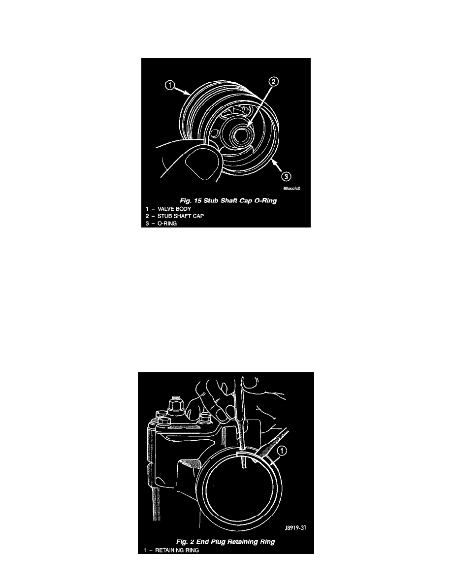
Fig. 15
5. Install O-ring into the back of the stub shaft cap.
6. Install stub shaft and valve assembly in the housing. Line up worm shaft to slots in the valve assembly
7. Install thrust support assembly.
NOTE: The thrust support is serviced as an assembly. If any component of the thrust support is damaged the assembly must be replaced.
8. Install adjuster nut and lock nut.
9. Adjust Thrust Bearing Preload and Over-Center Rotating Torque.
Steering Gear Housing Plug
STEERING GEAR HOUSING PLUG
REMOVAL