
RAM 2500 Truck 2WD L6-5.9L DSL Turbo VIN C (2002)
Wiper Relay: Testing and Inspection
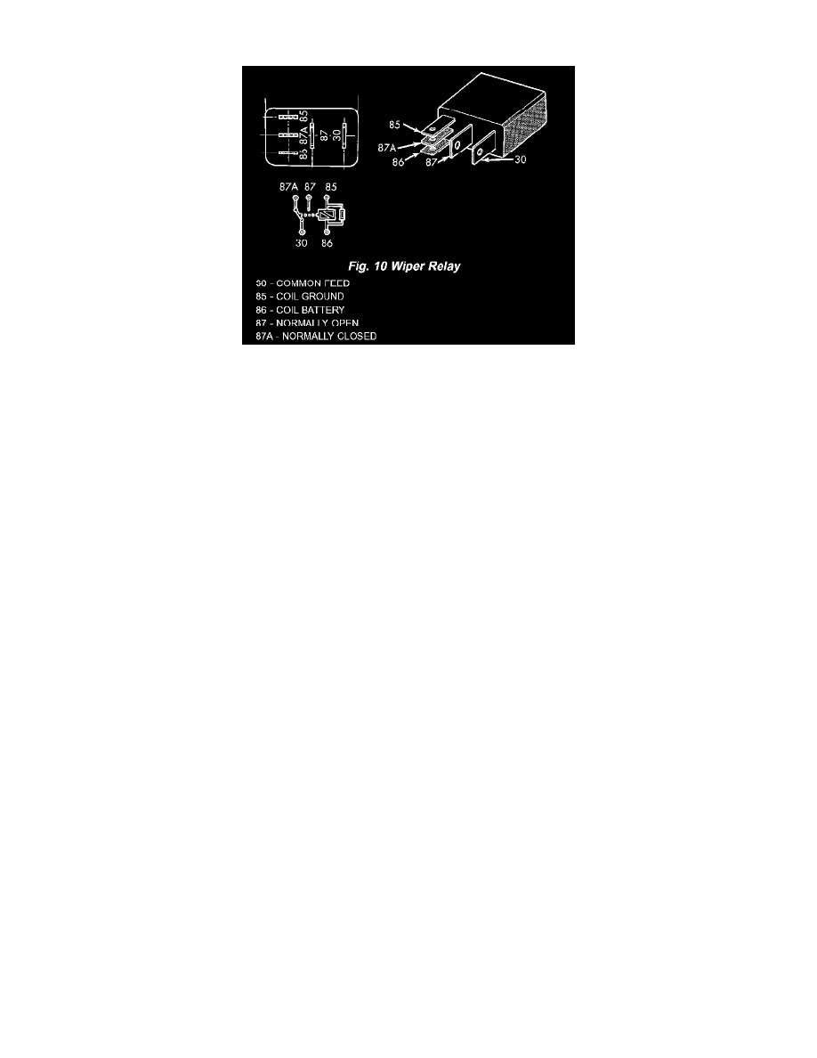
Fig. 10 Wiper Relay
The wiper relay (or intermittent wipe relay) is located in the Power Distribution Center (PDC) in the engine compartment. See the fuse and relay layout
label affixed to the inside surface of the PDC cover for wiper relay identification and location. Refer to the appropriate wiring information. The wiring
information includes wiring diagrams, proper wire and connector repair procedures, details of wire harness routing and retention, connector pin-out
information and location views for the various wire harness connectors, splices and grounds.
1. Remove the wiper relay from the PDC. (Refer to WIPERS/WASHERS/WIPER RELAY - REMOVAL See: Service and Repair).
2. A relay in the de-energized position should have continuity between terminals 87A and 30, and no continuity between terminals 87 and 30.
If OK, go to Step 3.
If not OK, replace the faulty relay.
3. Resistance between terminals 85 and 86 (electromagnet) should be 75 ± 5 ohms. If OK, go to Step 4. If not OK, replace the faulty relay.
4. Connect a battery to terminals 85 and 86. There should now be continuity between terminals 30 and 87, and no continuity between terminals 87A
and 30.
If OK, test the relay input and output circuits. Refer to RELAY CIRCUIT TEST.
If not OK, replace the faulty relay.
Relay Circuit Test
1. The relay common feed terminal cavity (30) is connected to the multi-function switch. There should be continuity between the receptacle for
terminal 30 of the wiper relay in the PDC and both driver low speed wiper motor driver circuit cavities of the instrument panel wire harness
connector for the multi-function switch at all times.
If OK, go to Step 2.
If not OK, repair the open driver low speed wiper motor driver circuit(s) between the PDC and the multi-function switch as required.
2. The relay normally closed terminal (87A) is connected to the wiper motor park switch through the wiper motor park switch sense circuit. There
should be continuity between the receptacle for terminal 87A of the wiper relay in the PDC and the wiper motor park switch sense circuit cavity of
the headlamp and dash wire harness connector for the wiper motor at all times.
If OK, go to Step 3.
If not OK, repair the open wiper motor park switch sense circuit between the PDC and the wiper motor as required.
3. The relay normally open terminal (87) is connected to a fused ignition switch output (run-acc) fuse in the Junction Block (JB) through a fused
ignition switch output (run-acc) circuit. There should be battery voltage at the receptacle for terminal 87 of the wiper relay in the PDC whenever
the ignition switch is in the ON or Accessory positions.
If OK, go to Step 4.
If not OK, repair the open fused ignition switch output (run-acc) circuit between the PDC and the JB as required.
4. The coil battery terminal (86) is connected to a fused ignition switch output (run-acc) fuse in the JB through a fused ignition switch output
(run-acc) circuit. There should be battery voltage at the receptacle for terminal 86 of the wiper relay in the PDC whenever the ignition switch is in
the ON or Accessory positions.
If OK, go to Step 5.
If not OK, repair the open fused ignition switch output (run-acc) circuit between the PDC and the JB as required.