
RAM 2500 Truck 2WD L6-6.7L DSL Turbo (2010)
NOTE: In this position, cylinders No. 2 and No. 5 can be serviced.
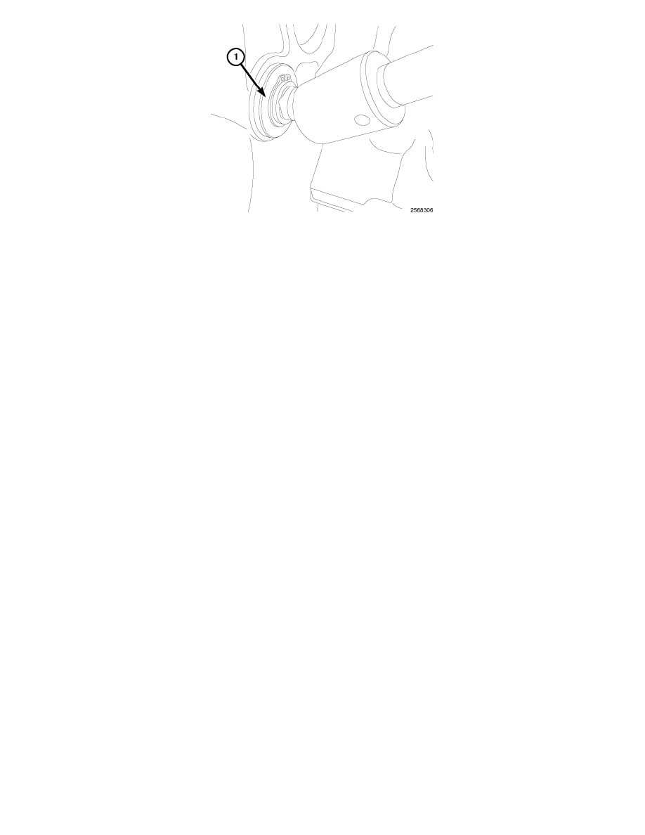
14. Using the barring tool 7471B (1), rotate the engine until the next crankshaft damper paint mark aligns with the mark you placed on the cover.
15. Repeat the valve spring compressing procedure previously performed and service the retainers, springs, and seals as necessary.
NOTE: In this position, cylinders No. 3 and No. 4 can be serviced.
16. Using the barring tool 7471B, rotate the engine until the next crankshaft damper paint mark aligns with the mark you placed on the cover.
17. Repeat the spring compressing procedure previously performed and service the retainers, springs, and seals as necessary.
Intake and Exhaust Valves - Installation
INSTALLATION
1. Install rocker housing. See: Valve Cover/Service and Repair/Removal and Replacement/Cylinder Head Cover(s) - Installation
2. Install fuel injectors and high pressure fuel linesSee: Powertrain Management/Fuel Delivery and Air Induction/Fuel Injector/Service and
Repair/Fuel Injector - Installation
3. Lubricate the valve tips and install the crossheads in their original locations.
4. Lubricate the crossheads and push rod sockets and install the rocker arms and pedestals in their original locations. Tighten bolts to 36 Nm (27 ft.
lbs.).
5. Verify valve lash adjustment See: Procedures.
6. Install cylinder head cover gasket onto rocker housingSee: Valve Cover/Service and Repair/Removal and Replacement/Cylinder Head Cover(s) -
Installation.
7. Install injector solenoid nuts.
8. Connect injector harness connectors.
9. Install cylinder head coverSee: Valve Cover/Service and Repair/Removal and Replacement/Cylinder Head Cover(s) - Installation.
10. Connect both negative battery cables.