
RAM 2500 Truck 2WD L6-6.7L DSL Turbo (2010)
1. Turn the ignition off.
2. Use the wiring application as a guide, trace the circuit being tested and locate the components related to the circuit.
3. Set your multimeter up to check for DC voltage.
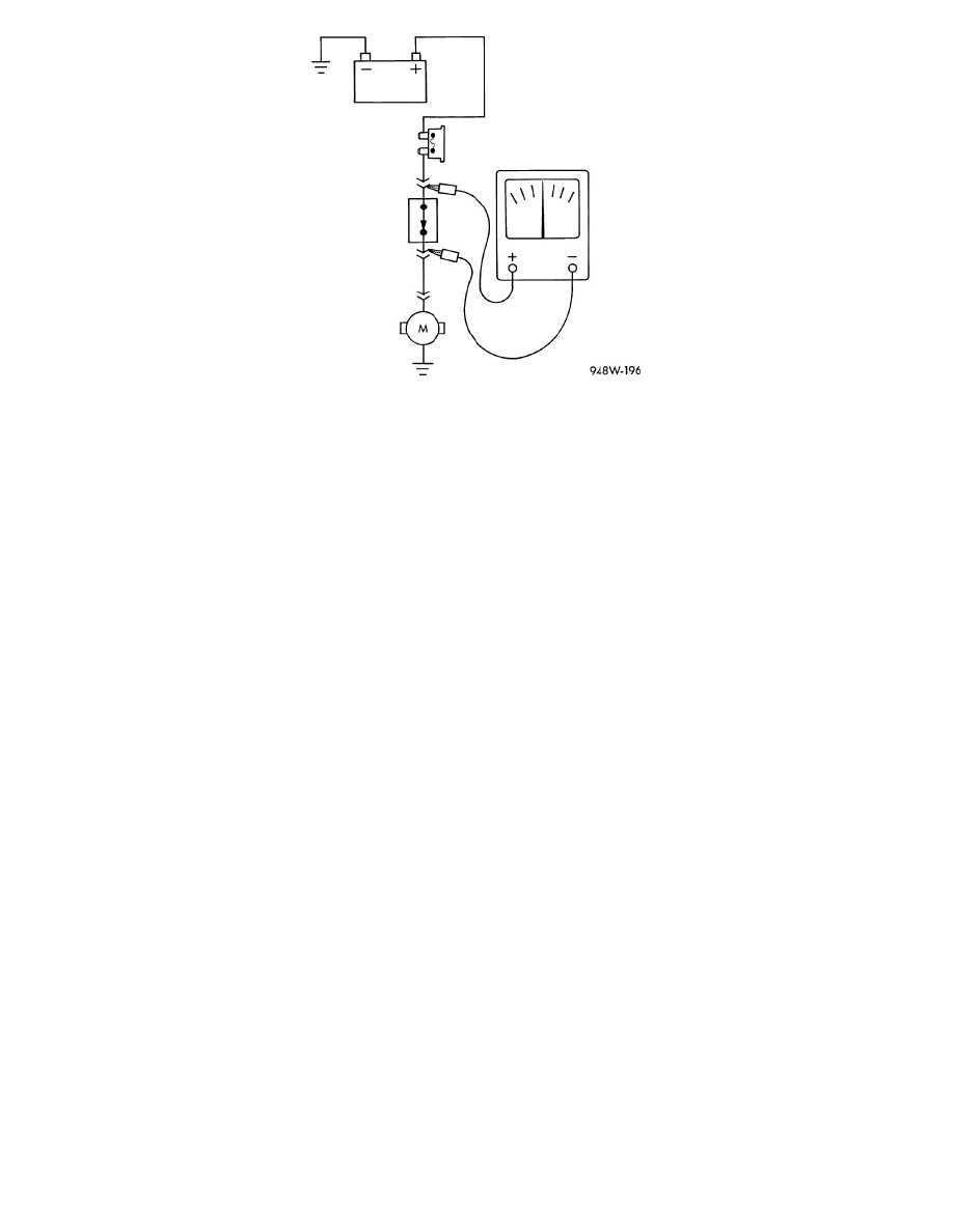
4. Carefully back probe the two component harness connectors of the circuit being tested.
WARNING: When the engine is operating, do not stand in direct line with the fan. Do not put your hands near the pulleys, belts or fan. Do not
wear loose clothing. Failure to follow these instructions may result in possible serious or fatal injury.
NOTE: If you are testing the starting circuit, disable the engine so the engine does not start.
5. Crank the engine for five seconds if you are testing the starting circuit and monitor the multimeter voltage reading.
6. For circuits that don't require the engine running, turn the ignition on.
7. For circuits that require the engine running, start the engine.
NOTE: If the circuit you are checking needs to be turned on, such as Blower Motor or a lamp, do so now.
8. Monitor the voltage reading.
9. The voltmeter will show the difference in voltage between the two points.
Is the voltage less than 0.4 of a Volt?
Yes
-
At this time the circuit is functioning properly. Continue to measure the voltage between the components and wiggle the wire harness and
connectors while checking for an intermittent condition.
-
Use the wiring application as a guide to trace the circuits and look for any in-line connectors where the excessive resistance could occur
intermittently.
-
Look for any chafed, pierced, pinched, or partially broken wires.
-
Look for broken, bent, pushed out or corroded terminals. Verify that there is good pin to terminal contact in the related wire harness connectors.
-
Perform any Technical Service Bulletins (TSBs) that may apply.
No
-
Repair the excessive resistance in the circuit.
-
Use the wiring application as a guide to trace the circuit and look for any in-line connectors where the excessive resistance may occur.
-
Look for any chafed, pierced, pinched, or partially broken wires.
-
Look for broken, bent, pushed out or corroded terminals. Verify that there is good pin to terminal contact in the related wire harness connectors.
-
Perform any Technical Service Bulletins (TSBs) that may apply.
Troubleshooting Wiring Problems
WIRING HARNESS TESTING
TROUBLESHOOTING TOOLS