
RAM 2500 Truck 2WD L6-6.7L DSL Turbo (2010)
Transmission Control System Relay: Diagnostic Aids
Electrostatic Discharge (ESD) Sensitive Devices
ELECTROSTATIC DISCHARGE (ESD) SENSITIVE DEVICES
All ESD sensitive components are solid state and a symbol is used to indicate this. When handling any component with this symbol, comply with the
following procedures to reduce the possibility of electrostatic charge build up on the body and inadvertent discharge into the component. If it is not
known whether the part is ESD sensitive, assume that it is.
1. Always touch a known good ground before handling the part. This should be repeated while handling the part and more frequently after sliding
across a seat, sitting down from a standing position, or walking a distance.
2. Avoid touching electrical terminals of the part, unless instructed to do so by a written procedure.
3. When using a voltmeter, be sure to connect the ground lead first.
4. Do not remove the part from it's protective packing until it is time to install the part.
5. Before removing the part from it's package, ground the package to a known good ground on the vehicle.
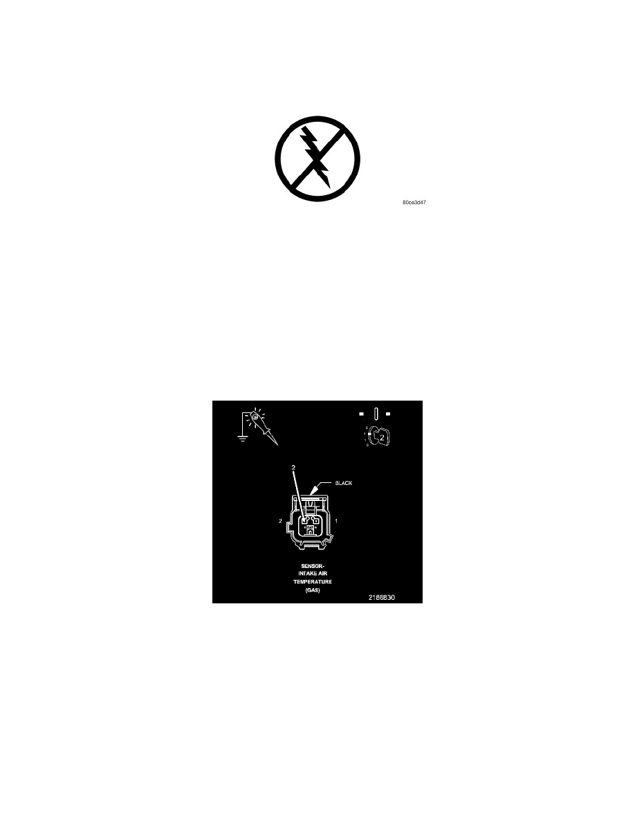
Check A Battery Or Ignition Voltage Circuit With A 12-Volt Test Light
CHECK A BATTERY OR IGNITION VOLTAGE CIRCUIT WITH A 12-VOLT TEST LIGHT
1. Turn the ignition off.
2. Disconnect the wire harness connector of the component that is receiving the voltage.
NOTE: Check connectors - Clean/repair as necessary.
3. At this time, leave all in-line connectors connected.
NOTE: Before inspecting any circuits, first test the 12-volt test light. Connect the 12-volt test light to battery ground or to any other known
good ground. Touch the lead of the test light to Battery +. If the test light is good, it should illuminate brightly.
4. Connect the 12-volt test light to a known good ground.
5. Use the test light lead to carefully probe the Battery or Ignition Voltage circuit in the harness connector.
6. First check with the ignition off, next check with the ignition on, and lastly check while cranking the engine.
Does the test light illuminate brightly?