
RAM 2500 Truck 2WD L6-6.7L DSL Turbo (2010)
2. Disconnect the Negative Battery cable (ground).
3. Using a multimeter, set the multimeter leads up to properly measure Amperage.
4. Connect the ground lead that is plugged into the COM port of the multimeter to the Negative Battery cable.
5. Connect the other lead of the multimeter that is plugged into the Amp port of the multimeter to the negative battery post/terminal.
CAUTION: Do not crank the engine or turn on any accessories that may draw more than 10 Amps. You may open the protective fuse in the
multimeter.
NOTE: To get a more accurate reading and current draw, wait 20 minutes to make sure all modules have powered down before continuing.
Some modules may stay powered up longer than others.
6. While monitoring the amperage reading, remove a fuse and see if the amperage drops.
7. If the amperage does not drop, install that fuse you just removed and remove the next fuse.
Does the amperage drop to between 0.02 to 0.04 of an Amp when removing any fuses.
Yes
-
Use the wiring application as a guide to find out what components or modules are powered by the fuse. At this point you can install the fuse and
begin disconnecting the components powered by the fuse. When the amperage drops after disconnecting a component you will know which
component is at fault. It is important to know how long some modules are supposed to remain awake. You don't want to replace a component that
is operating normally.
No
-
The condition that originally caused the draw may not be present at this time.
-
Look for any chafed, pierced, pinched, or partially broken wires.
-
Look for broken, bent, pushed out or corroded ground terminals.
-
Perform any Technical Service Bulletins that may apply.
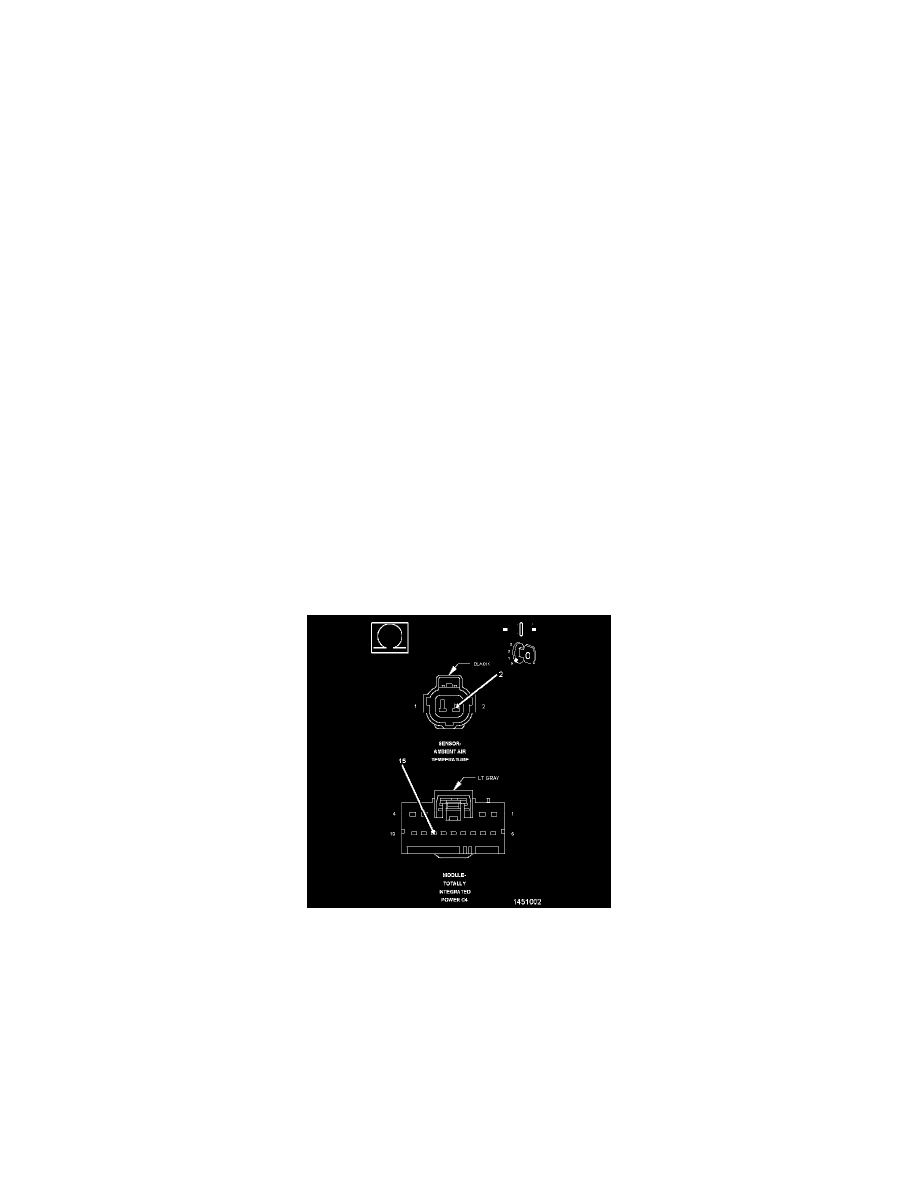
Check The Resistance In A Circuit Using An Ohm Meter
CHECK THE RESISTANCE IN A CIRCUIT USING AN OHM METER
NOTE: This is not the best way of checking for an open ground circuit. When checking for an open in a ground circuit, perform the Check a
Ground Circuit for an Open Using a 12-Volt Test Light diagnostic procedure See: Troubleshooting Tests/Check A Ground Circuit
For An Open Using A 12-Volt Test Light.
1. Turn the ignition off.
2. Disconnect the wire harness connectors of the components that contain the circuit suspected as being open.
NOTE: Check connectors - Clean/repair as necessary.
3. At this time leave all in-line connectors connected.
NOTE: Before measuring the resistance of any circuit, first measure the resistance between the two leads of the multimeter. Take this value
and subtract it from the value recorded when measuring the resistance of the circuit being checked. The leads of the meter can add up