
RAM 2500 Truck 2WD V10-8.0L VIN W (2003)
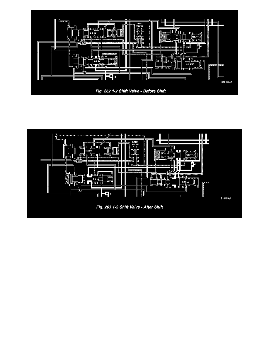
The 1-2 shift valve assembly (Fig. 262), or mechanism, consists of: the 1-2 shift valve, governor plug, and a spring on the end of the valve. After the
manual valve has been placed into a forward gear range, line pressure is directed to the 1-2 shift valve. As the throttle is depressed, throttle pressure is
applied to the right side of the 1-2 shift valve assembly. With throttle pressure applied to the right side of the valve, there is now both spring pressure
and throttle pressure acting on the valve, holding it against the governor plug. As the vehicle begins to move and build speed, governor pressure is
created and is applied to the left of the valve at the governor plug.
When governor pressure builds to a point where it can overcome the combined force of the spring and throttle pressure on the other side of the valve,
the valve will begin to move over to the right. As the valve moves to the right, the middle land of the valve will close off the circuit supplying the
throttle pressure to the right side of the valve. When the throttle pressure is closed off, the valve will move even farther to the right, allowing line
pressure to enter another circuit and energize the front servo, applying the front band (Fig. 263).
The governor plug serves a dual purpose:
-
It allows the shift valves to move either left or right, allowing both upshifts and downshifts.
-
When in a manual selection position, it will be hydraulically "blocked" into position so no upshift can occur.
The physical blocking of the upshift while in the manual "1" position is accomplished by the directing of line pressure between both lands of the
governor plug. The line pressure reacts against the larger land of the plug, pushing the plug back against the end plate overcoming governor pressure.
With the combination of the line pressure and spring pressure, the valve cannot move, preventing any upshift.
1-2 SHIFT CONTROL VALVE
It contains a valve with four lands and a spring. It is used as both a "relay" and "balanced" valve.