
RAM 2500 Truck 2WD V10-8.0L VIN W MDC (1999)
Antenna Cable Routing
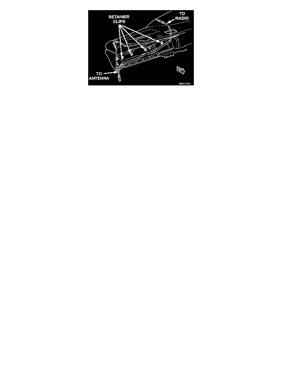
6. Reach through the glove box opening to disengage the antenna cable from the retainer clips on the back of the instrument panel.
7. Remove the radio receiver from the instrument panel. Refer to Radio Receiver in the Replacement for the procedures.
8. Pull the antenna cable out through the radio receiver opening in the instrument panel.
9. Untie the cord or twine from the instrument panel antenna cable connector, leaving the cord or twine in place of the cable in the instrument
panel.
10. Remove the antenna cable from the instrument panel.
INSTALLATION
Antenna Body And Cable
1. The the end of the cord or twine that was used during antenna body and cable removal securely to the connector on the end of the antenna
coaxial cable being installed into the vehicle. This cord will be used to pull or "fish" the cable back into position.
2. Position the antenna body and cable into the vehicle.
3. Using the cord or twine, pull the antenna coaxial cable through the hole in the right cowl side reinforcement into the engine compartment.
4. Again using the cord or twine, pull the antenna coaxial cable from the engine compartment through the hole in the dash panel and into the
passenger compartment.
5. Reach above the Powertrain Control Module (PCM) on the right side of the dash panel in the engine compartment to engage the antenna
coaxial cable grommet into the hole in the dash panel.
6. Position the antenna body through the top of the fender.
7. Install the adapter over the antenna body from the top of the fender.
8. Install and tighten the antenna cap nut using an antenna nut wrench (Special Tool C-4816). Tighten the antenna cap nut to 8 Nm (70 in lbs).
9. Install and tighten the antenna mast onto the antenna body. Tighten the mast to 3.3 Nm (30 in lbs).
10. Reach under the passenger side of the instrument panel near the right cowl side inner panel to reconnect the two halves of the radio antenna
coaxial cable connector. Wrap the connection with a piece of foam tape.
11. Engage the coaxial cable connector with the retainer clip located on the bottom of the heater-A/C housing.
12. Reconnect the battery negative cable.
Instrument Panel Antenna Cable
1. The the end of the cord or twine that was used during instrument panel antenna cable removal securely to the connector on the end of the
antenna cable being installed into the instrument panel. This cord will be used to pull or "fish" the cable back into position.
2. Using the cord or twine, pull the antenna cable through the radio receiver opening from under the instrument panel.
3. Install the radio receiver onto the instrument panel. Refer to Radio Receiver in the Replacement for the procedures.
4. Reach through the glove box opening to engage the antenna cable with the retainer clips on the back of the instrument panel.
5. Install the glove box onto the instrument panel. Refer to Glove Box in the Replacement of Instrument Panel Systems for the procedures.
6. Untie the cord or twine from the instrument panel antenna cable connector.
7. Reach under the passenger side of the instrument panel near the right cowl side inner panel to reconnect the two halves of the radio antenna
coaxial cable connector. Wrap the connection with a piece of foam tape.
8. Engage the coaxial cable connector with the retainer clip located on the bottom of the heater-A/C housing.
9. Reconnect the battery negative cable.