
RAM 2500 Truck 2WD V10-8.0L VIN W MDC (1999)
Clockspring Assembly / Spiral Cable: Service and Repair
The clockspring cannot be repaired. It must be replaced if faulty or damaged, or if the driver side airbag has been deployed.
WARNING: THE AIRBAG SYSTEM IS A SENSITIVE, COMPLEX ELECTROMECHANICAL UNIT. BEFORE ATTEMPTING TO
DIAGNOSE OR SERVICE ANY AIRBAG SYSTEM OR RELATED STEERING WHEEL, STEERING COLUMN, OR INSTRUMENT
PANEL COMPONENTS YOU MUST FIRST DISCONNECT AND ISOLATE THE BATTERY NEGATIVE (GROUND) CABLE. THEN
WAIT TWO MINUTES FOR THE SYSTEM CAPACITOR TO DISCHARGE BEFORE FURTHER SYSTEM SERVICE. THIS IS THE
ONLY SURE WAY TO DISABLE THE AIRBAG SYSTEM. FAILURE TO DO THIS COULD RESULT IN ACCIDENTAL AIRBAG
DEPLOYMENT AND POSSIBLE PERSONAL INJURY.
REMOVAL
NOTE: Before starting this procedure, be certain to turn the steering wheel until the front wheels are in the straight-ahead position.
1. Place the front wheels in the straight-ahead position.
2. Remove the driver side airbag module from the steering wheel. Refer to Driver Side Airbag Module in the Replacement for the procedures.
3. If the vehicle is so equipped, disconnect the clockspring wire harness connectors from the vehicle speed control switches and the remote radio
switches located within the hub cavity of the steering wheel.
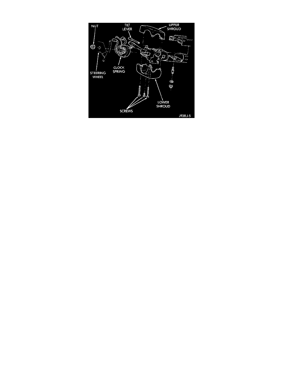
4. Remove the nut that secures the steering wheel armature to the steering column upper shaft, which is located within the hub cavity of the steering
wheel.
5. Pull the steering wheel off of the steering column upper shaft spline using a steering wheel puller (Special Tool C-3428-B).
6. Remove the steering column opening cover from the instrument panel. Refer to Steering Column Opening Cover in the Replacement of Instrument
Panel Systems for the procedures.
7. If the vehicle is so equipped, unscrew the lever from the tilt steering column adjuster mechanism located on the left side of the column just below
the multi-function switch stalk.
8. Remove both the upper and lower shrouds from the steering column.
9. Remove the lower fixed column shroud from the steering column.
10. Disconnect the instrument panel wire harness connector from the lower clockspring connector receptacle.
11. Disconnect the lower clockspring wire harness connector from the instrument panel wire harness, located on the instrument panel lower
reinforcement below the steering column.
12. Carefully disengage the plastic latches of the clockspring assembly from the steering column lock housing and remove the clockspring from the
column. The clockspring cannot be repaired. It must be replaced if faulty or damaged, or if the driver side airbag has been deployed.
INSTALLATION
If the clockspring is not properly centered in relation to the steering wheel, steering shaft and steering gear, it may be damaged. Refer to Clockspring
Centering in the Adjustments before installing or reinstalling a clockspring.
Service replacement clockspring are shipped precentered and with a piece of tape covering the depressed clockspring auto-locking tabs. This tape
should not be removed until the clockspring has been installed on the steering column. If the tape is removed before the clockspring is installed on a
steering column, the clockspring centering procedure must be performed.
NOTE: Before starting this procedure, be certain that the front wheels are still in the straight-ahead position.
1. Carefully slide the centered clockspring down over the steering column upper shaft until the clockspring latches engage the steering column lock
housing.