
RAM 2500 Truck 2WD V8-5.2L VIN Y (2000)
The self-calibrating compass unit requires no adjusting in normal use. The compass unit will compensate for magnetism the body of the vehicle
may acquire during normal use. However, avoid placing anything magnetic directly on the roof of the vehicle. Magnetic mounts for an antenna, a
repair order hat, or a funeral procession flag can exceed the compensating ability of the compass unit if placed on the roof panel. If the vehicle
roof should become magnetized, the demagnetizing and calibration procedures found in this may be required to restore proper compass operation.
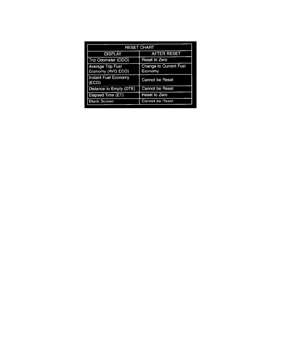
Reset Chart
THERMOMETER
The thermometer displays the outside ambient temperature in whole degrees. The temperature display can be changed from Fahrenheit to Celsius
using the U. S./Metric push button. The displayed temperature is not an instant reading of conditions, but an average temperature. It may take the
thermometer display several minutes to respond to a major temperature change, such as driving out of a heated garage into winter temperatures.
When the ignition switch is turned to the OFF position, the last displayed temperature reading stays in the thermometer unit memory. When the
ignition switch is turned to the ON position again, the thermometer will display the memory temperature if the engine coolant temperature is above
about 43 °C (109 °F). If the engine coolant temperature is below about 43 °C (109 °F), the thermometer will display the actual temperature sensed
by the ambient temperature sensor. The thermometer temperature display update interval varies with the vehicle speed; therefore, if the
temperature reading seems inaccurate, drive the vehicle for at least three minutes while maintaining a speed of 48 km/h (30 mph) or higher.
The thermometer function is supported by an ambient temperature sensor. The sensor is mounted outside the passenger compartment near the front
and center of the vehicle, and is hard wired to the module. The ambient temperature sensor is available as a separate service item.
The Compass Mini-Trip Computer only operates with the ignition switch in the ON position. When the ignition switch is turned to the ON
position, all of the segments in the Compass Mini-Trip Computer VFD will be turned on for one second, then the display will return to the last
function being displayed before the ignition was turned to the OFF position. With the ignition switch in the ON position, momentarily depressing
and releasing the Step push button switch will cause the compass-mini-trip computer to change its mode of operation, and momentarily depressing
and releasing the U. S./Metric push button will cause the unit to toggle between U. S. and Metric measurements. While in either compass mode,
depressing the U. S./Metric push button for more than ten seconds will toggle the display between the compass/temperature and the
compass/compass in degrees modes.
This Compass Mini-Trip Computer features several functions that can be reset. If both the Step and U. S./Metric push buttons are depressed at the
same time with the ignition switch in the ON position, the trip computer information that can be reset is reset. Depressing and releasing the Step
and U. S./Metric push buttons at the same time for more than 100 milliseconds, but not more than one second while in any display mode (except
the compass/temperature mode) will cause a local reset. A local reset affects only the function currently displayed. See the Reset Chart below for
more information on this feature. Performing a local reset while in the compass/temperature mode enters the module into the compass variance
setting mode.
Depressing and releasing the Step and U.S./Metric push buttons at the same time for more than two seconds while in any display mode (except the
compass/temperature mode) will cause a global reset. A global reset changes all of the trip computer functions that can be reset.
For more information on the features and control functions of the Compass Mini-Trip Computer, see the owner's manual in the vehicle glove box.
OVERHEAD CONSOLE READING AND COURTESY LAMP
The overhead console in this vehicle is equipped with two individual reading and courtesy lamps. The lamp lenses are the only visible components
of these lamps. The reading and courtesy lamp lenses are mounted in the overhead console housing between the garage door opener storage bin
and the sunglasses storage bin. Each lamp has its own switch, bulb, reflector and lens; but both lamps share a common lamp housing within the
overhead console.
The overhead console reading and courtesy lamps operate on battery current that is provided at all times, regardless of the ignition switch position.
The ground feed for the lamps is switched through the integral reading and courtesy lamp switches or through the door jamb switches. Each lamp
is designed and aimed to provide illumination that will be directed only to that side of the vehicle on which the lamp is located.