
RAM 2500 Truck 2WD V8-5.2L VIN Y (2000)
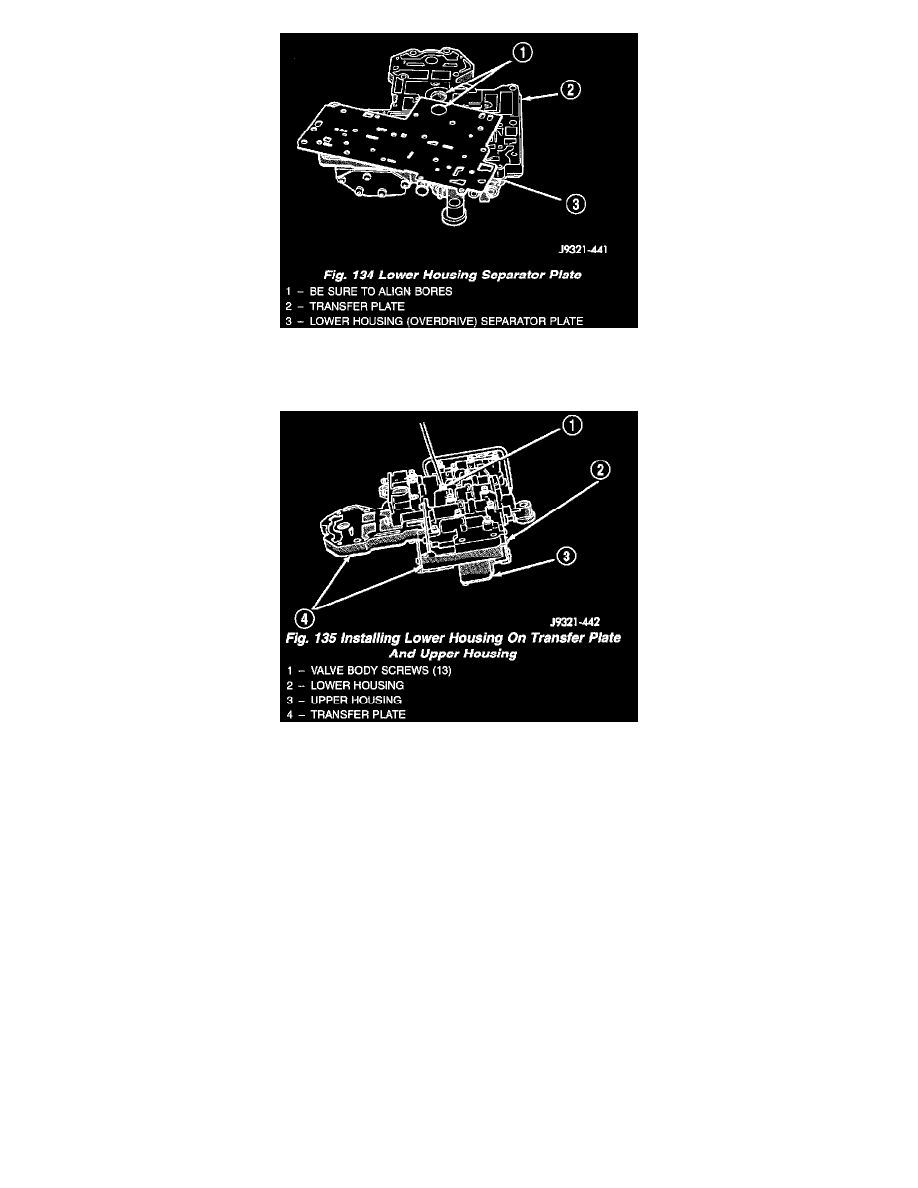
Fig. 134
4. Position lower housing separator plate on transfer plate (Fig. 134).
Fig. 135
5. Install lower housing on assembled transfer plate and upper housing (Fig. 135).
6. Install and start all valve body screws by hand except for the screws to hold the boost valve tube brace. Save those screws for later installation.
Then tighten screws evenly to 4 Nm (35 in. lbs.) torque. Start at center and work out to sides when tightening screws (Fig. 135).
UPPER HOUSING VALVE AND PLUG