
RAM 2500 Truck 2WD V8-5.7L VIN D (2004)
11.
Reinstall the PCM. Tighten the PCM mounting bracket fasteners.
^
For CS/RS/JR vehicles, tighten the mounting bolts to 35 in-lbs (4 N.m).
^
For KJ/PT vehicles, tighten the mounting bolts to 100 in-lbs (11.3 N.m).
^
For DR vehicles, tighten the mounting bolts to 75 in-lbs (8.5 N.m) and the nuts to 60 in-lbs (6.8 N.m).
12.
For CS and RS Vehicles only: Install the left wheel well splash shield.
13.
For CS and RS Vehicles only: Lower the vehicle.
14.
For PT and DR vehicles only: Install the air cleaner assembly.
15.
Connect the negative battery cable.
B. Replace PCM
NOTE:
Only those vehicles that have water and/or corrosion found during the inspection in Section A. require PCM replacement. Very few vehicles are
expected to require PCM replacement.
1.
Disconnect the remaining PCM electrical connectors.
2.
Remove the three (3) PCM-to-bracket bolts, then remove the PCM from the bracket and set it aside for return to the Warranty Material Return
Center.
3.
Install the new PCM on the bracket.
^
For CS/RS/KJ/JR/DR vehicles, tighten the mounting bolts to 35 in-lbs (4 N.m).
^
For PT vehicles, tighten the mounting bolts to 105 in-lbs (11.8 N.m).
4.
Reinstall the PCM onto the vehicle. Tighten the PCM mounting bracket fasteners.
^
For CS/RS/JR vehicles, tighten the mounting bolts to 35 in-lbs (4 N.m).
^
For KJ/PT vehicles, tighten the mounting bolts to 100 in-lbs (11.3 N.m).
^
For DR vehicles, tighten the mounting bolts to 75 in-lbs (8.5 N.m) and the nuts to 60 in-lbs (6.8 N.m)
5.
^
If only the PCM required replacement (DR/KJ vehicles with a Motorola PCM), carefully reconnect the PCM connector(s). This may take
several attempts. Be sure to insert the connector straight into the module. If the connector is not inserted straight into the module, it may cause
the seal to move out of place. Verify that all seals are in place (Figure 2) and then continue with Section F - PCM/Vehicle Data Set-up.
^
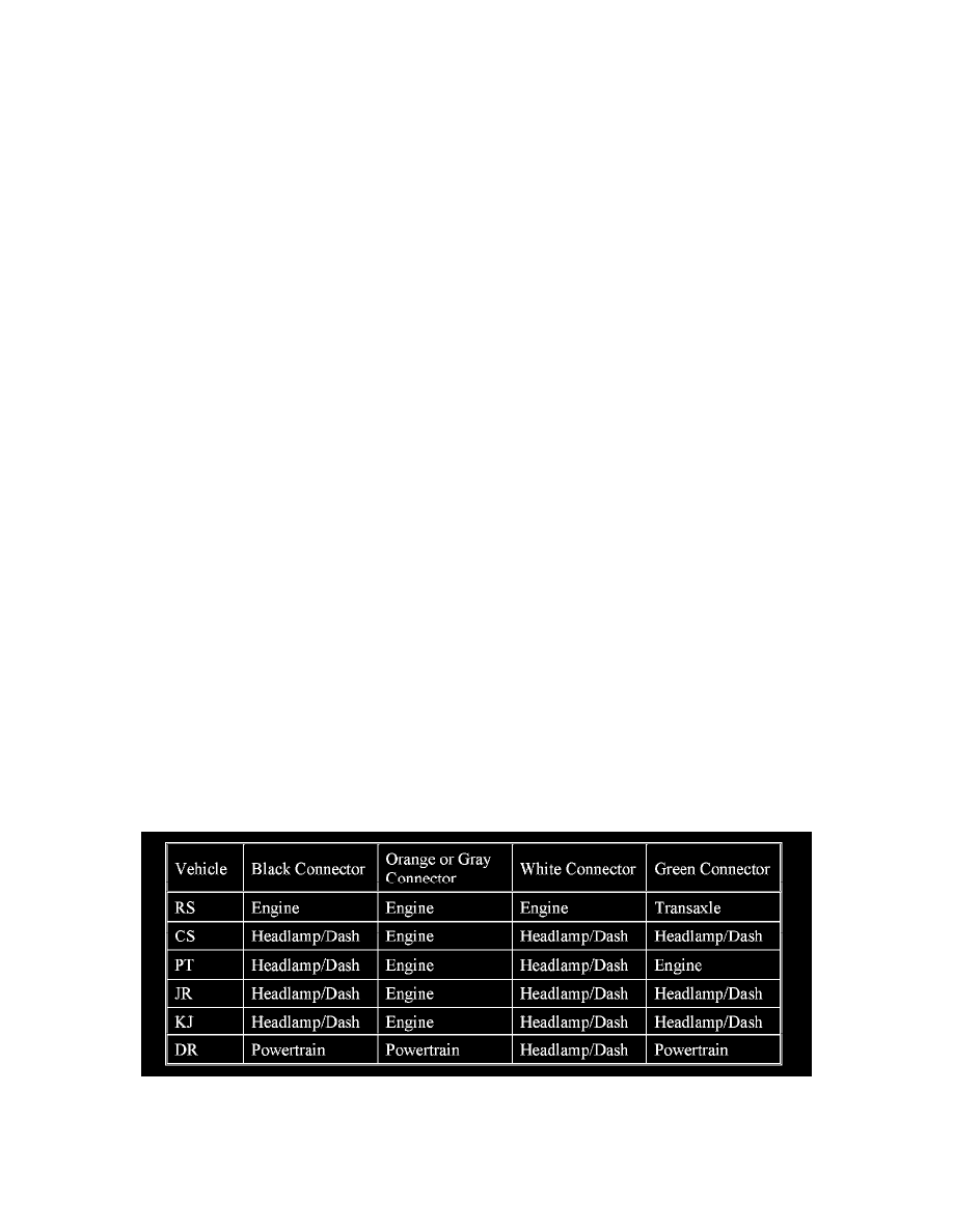
If one of the PCM wiring harnesses required replacement, continue with the applicable section, Section C - Replace Transaxle Wiring Harness,
Section D - Replace Engine/Powertrain Wiring Harness or Section E - Replace Headlamp & Dash Wiring Harness. Refer to the table to
correlate the PCM connector color to the harness type.
C. Replace Transaxle Wiring Harness - RS Only