
RAM 2500 Truck 2WD V8-5.9L VIN Z (1997)
Compressor Clutch Relay: Testing and Inspection
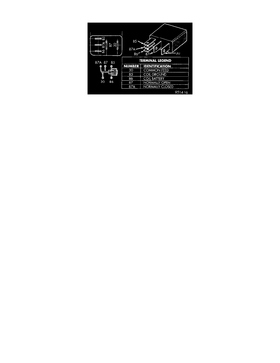
Compressor Clutch Relay
RELAY TEST
The compressor clutch relay is located in the Power Distribution Center (PDC). Refer to the PDC label for relay identification and location. Remove the
relay from the PDC to perform the following tests:
1. A relay in the de-energized position should have continuity between terminals 87A and 30, and no continuity between terminals 87 and 30. If OK,
go to Step 2. If not OK, replace the faulty relay.
2. Resistance between terminals 85 and 86 (electromagnet) should be 75 +/-5 ohms. If OK, go to Step 3. If not OK, replace the faulty relay.
3. Connect a battery to terminals 85 and 86. There should now be continuity between terminals 30 and 87, and no continuity between terminals 87A
and 30. If OK, SEE the Relay Circuit Test. If not OK, replace the faulty relay.
RELAY CIRCUIT TEST
1. The relay common feed terminal cavity (30) is connected to fused battery feed. There should be battery voltage at the cavity for relay terminal 30
at all times. If OK, go to Step 2. If not OK, repair the open circuit to the PDC fuse as required.
2. The relay normally closed terminal (87A) is not used in this application. Go to Step 3.
3. The relay normally open terminal cavity (87) is connected to the compressor clutch coil. There should be continuity between this cavity and the
A/C compressor clutch relay output circuit cavity of the compressor clutch coil wire harness connector. If OK, go to Step 4. If not OK, repair the
open circuit as required.
4. The relay coil battery terminal (86) is connected to the fused ignition switch output (run/start) circuit. There should be battery voltage at the cavity
for relay terminal 86 with the ignition switch in the On position. If OK, go to Step 5. If not OK, repair the open circuit to the fuse block module as
required.
5. The coil ground terminal cavity (85) is switched to ground through the Powertrain Control Module (PCM). There should be continuity between
this cavity and the A/C compressor clutch relay control circuit cavity of the PCM wire harness connector C (gray) at all times. If not OK, repair the
open circuit as required.