
RAM 2500 Truck 4WD L6-5.9L DSL Turbo VIN 6 (1999)
Drive/Propeller Shaft: Description and Operation
Propeller Shafts
The function of a propeller shaft is to transmit power from one point to another in a smooth action. The shaft is designed to send torque through an
angle from the transmission (transfer case on 4WD vehicles) to the axle.
The propeller shaft must operate through constantly changing relative angles between the transmission and axle. It must also be capable of changing
length while transmitting torque. The axle rides suspended by springs in a floating motion. This means the propeller shaft must be able to change
angles when going over various roads. This is accomplished through universal joints, which permit the propeller shaft to operate at different angles.
The slip joints (or yokes) permit contraction or expansion.
Tubular propeller shafts are balanced by the manufacturer with weights spot welded to the tube.
Before undercoating a vehicle, the propeller shaft and the U-joints should be removed if possible. If removal is not possible, make sure that the
propeller shaft and U-joints are fully covered. This will prevent the undercoating from causing an out of balance condition and vibration.
CAUTION: Use exact replacement parts for attaching the propeller shafts to ensure safe operation. The specified torque must always be applied
when tightening the fasteners.
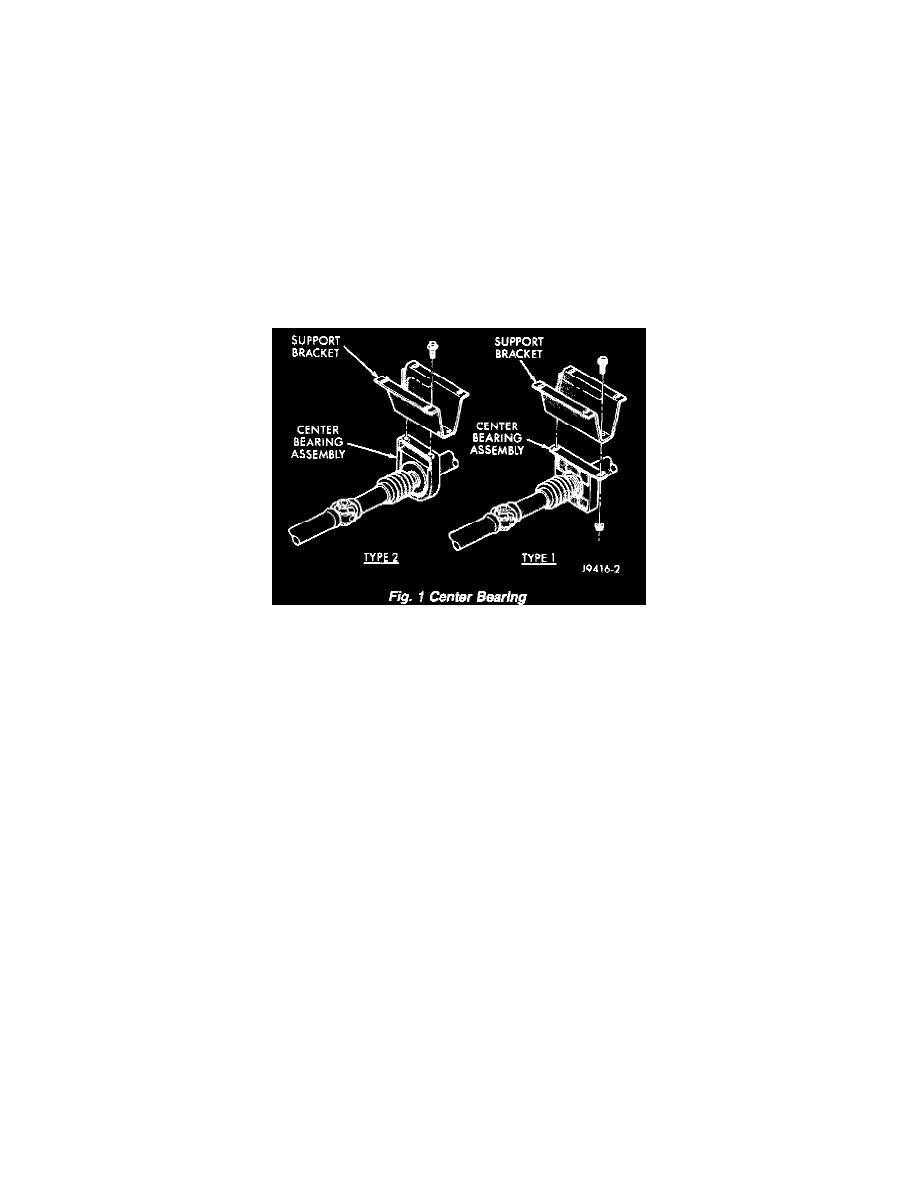
Center Bearing
Fig. 1
The two-piece propeller shaft uses a center bearing to support the shafts. Two types of center bearings are used. Type 1 is used with the 9 1/4 axle.
Type 2 is used with the Dana axles. Both types are mounted in the same location.
Lubrication
The factory installed universal joints are lubricated for the life of the vehicle. All universal joints should be inspected for leakage and damage each
time the vehicle is serviced. If seal leakage or damage exists, the universal joint should be replaced. Refer to Maintenance, for additional information.
Propeller Shaft Joint Angle
When two shafts come together at a common joint, the bend that is formed is called the operating angle. The larger the angle, the larger the amount of
angular acceleration and deceleration of the joint. This speeding up and slowing down of the joint must be canceled to produce a smooth power flow.
This is done through the phasing of a propeller shaft and ensuring that the proper propeller shaft joint working angles are maintained.
A propeller shaft is properly phased when the yoke ends are in the same plane, or in line. A twisted shaft will make the yokes out of phase and cause a
noticeable vibration.
When taking propeller shaft joint angle measurements, or checking the phasing, of two piece shafts, consider each shaft separately.
Ideally the driveline system should have:
-
Angles that are equal or opposite within 1 degree of each other.
-
Have a 3 degree maximum operating angle.
-
Have at least a 1/2 degree continuous operating (propeller shaft) angle.