
RAM 2500 Truck 4WD L6-5.9L DSL Turbo VIN 7 (2001)
Seat Heater Switch: Testing and Inspection
Driver Seat Heater Switch Test
WARNING: ON VEHICLES EQUIPPED WITH AIRBAGS, DISABLE THE AIRBAG SYSTEM BEFORE ATTEMPTING ANY STEERING
WHEEL, STEERING COLUMN, OR INSTRUMENT PANEL COMPONENT DIAGNOSIS OR SERVICE. DISCONNECT AND ISOLATE
THE BATTERY NEGATIVE (GROUND) CABLE, THEN WAIT TWO MINUTES FOR THE AIRBAG SYSTEM CAPACITOR TO
DISCHARGE BEFORE PERFORMING FURTHER DIAGNOSIS OR SERVICE. THIS IS THE ONLY SURE WAY TO DISABLE THE
AIRBAG SYSTEM. FAILURE TO TAKE THE PROPER PRECAUTIONS COULD RESULT IN ACCIDENTAL AIRBAG DEPLOYMENT
AND POSSIBLE PERSONAL INJURY.
1. If the problem being diagnosed involves inoperative heated seat switch back lighting and the cluster illumination lamps operate, go to Step 2. If the
problem being diagnosed involves inoperative heated seat switch back lighting and the cluster illumination lamps are also inoperative, refer to
Instrument Cluster for the proper cluster illumination lamps diagnosis and testing procedures. If the problem being diagnosed involves inoperative
heated seat switch indicator lamps and the heated seat elements do not heat, refer to Step 4. If the problem being diagnosed involves inoperative
heated seat switch indicator lamps and the heated seat elements do heat, go to Step 8. If the problem being diagnosed involves a heated seat switch
indicator lamp that remains illuminated after the heated seat has been turned OFF, refer to Heated Seat Module in Electronic Control Modules for
the location of the proper heated seat module diagnosis and testing procedures. Also refer to the Body Diagnostic for additional diagnosis and
testing procedures.
2. Disconnect and isolate the battery negative cable. Remove the heated seat switch and bezel unit from the instrument panel. Disconnect the
instrument panel wire harness connector from the connector receptacle on the back of the heated seat switch to be tested. Check for continuity
between the ground circuit cavity of the instrument panel wire harness connector for the heated seat switch and a good ground. There should be
continuity. If OK, go to Step 3. If not OK, repair the open ground circuit to ground as required.
3. Reconnect the battery negative cable. Turn the park lamps ON with the headlamp switch. Rotate the panel lamps dimmer thumb wheel on the
headlamp switch upward to just before the interior lamps detent. Check for battery voltage at the fused panel lamps dimmer switch signal circuit
cavity of the instrument panel wire harness connector for the heated seat switch. If OK, replace the faulty heated seat switch. If not OK, repair the
open fused panel lamps dimmer switch signal circuit to the fuse in the Junction Block (JB) as required.
4. Check the fused ignition switch output (run) fuse in the Junction Block (JB). If OK, go to Step 5. If not OK, repair the shorted circuit or
component as required and replace the faulty fuse.
5. Turn the ignition switch to the ON position. Check for battery voltage at the fused ignition switch output (run) fuse in the JB. If OK, go to Step 6.
If not OK, repair the open fused ignition switch output (run) circuit to the ignition switch as required.
6. Disconnect and isolate the battery negative cable. Remove the heated seat switch and bezel unit from the instrument panel. Disconnect the
instrument panel wire harness connector from the connector receptacle on the back of the heated seat switch to be tested. Reconnect the battery
negative cable. Turn the ignition switch to the ON position. Check for battery voltage at the fused ignition switch output (run) circuit cavity of the
instrument panel wire harness connector for the heated seat switch. If OK, go to Step 7. If not OK, repair the open fused ignition switch output
(run) circuit to the JB fuse as required.
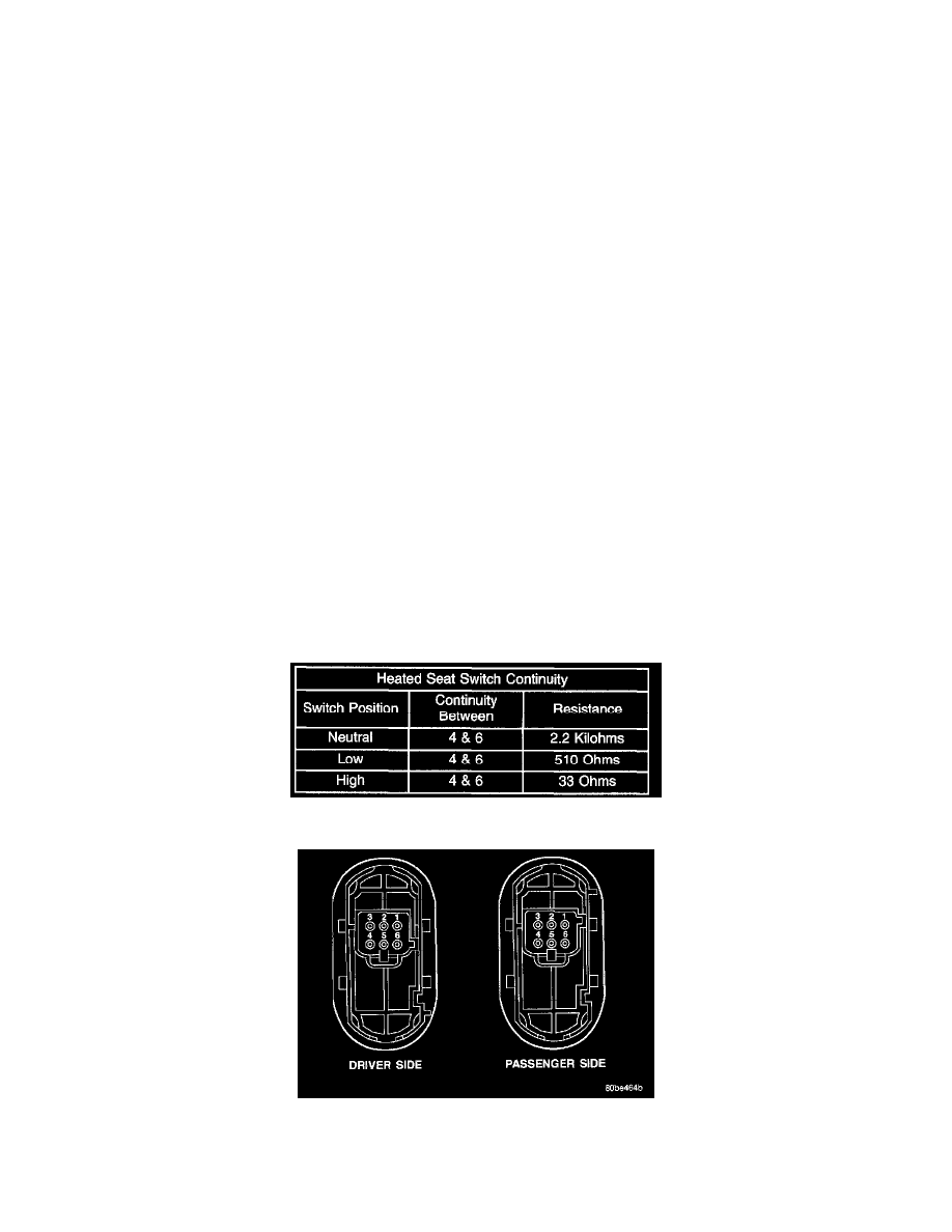
Heated Seat Switch Continuity
Heated Seat Switch
7. Check the continuity and resistance values of the heated seat switch in the Neutral, Low and High positions as shown in the Heated Seat Switch
Continuity chart. If OK, refer to Heated Seat Module in Electronic Control Modules for the location of the proper heated seat module diagnosis