
RAM 2500 Truck 4WD L6-5.9L DSL Turbo VIN 7 (2001)
Fuse Block: Service and Repair
REMOVAL
1. Disconnect and isolate the battery negative cable.
2. Roll down the instrument panel from the dash panel, but do not remove it from the vehicle. Refer to Instrument Panel Assembly for the instrument
panel assembly removal procedures.
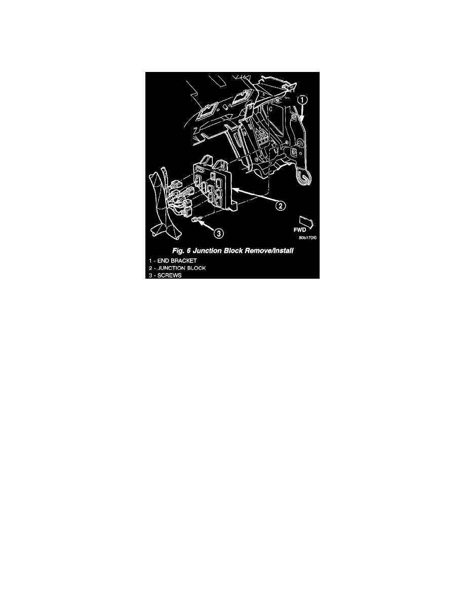
Fig.6 Junction Block Remove/Install
3. Reach through the outboard side of the instrument panel steering column opening to access and disconnect all of the wire harness connectors from
the Junction Block (JB) connector receptacles (Fig.6).
4. Reach through the outboard side of the instrument panel steering column opening to access and remove the two screws that secure the JB to the
left instrument panel end bracket.
5. Reach through the outboard side of the instrument panel steering column opening to remove the JB from the left instrument panel end bracket.
INSTALLATION
NOTE: If the Junction Block (JB) is being replaced with a new unit, be certain to transfer each of the fuses, circuit breakers and relays from the
faulty JB to the proper cavities of the replacement JB. Refer to Junction Block for the location of complete circuit diagrams and cavity assignments for
the JB.
1. Reach through the outboard side of the instrument panel steering column opening to position the JB onto the left instrument panel end bracket.
2. Reach through the outboard side of the instrument panel steering column opening to install and tighten the two screws that secure the JB to the left
instrument panel end bracket. Tighten the screws to 2.85 Nm (25 in. lbs.).
3. Reach through the outboard side of the instrument panel steering column opening to access and reconnect all of the wire harness connectors to the
JB connector receptacles.
4. Install the instrument panel onto the dash panel. Refer to Instrument Panel Assembly for the location of the instrument panel assembly installation
procedures.
5. Reconnect the battery negative cable.