
RAM 2500 Truck 4WD L6-5.9L DSL Turbo VIN 7 (2001)
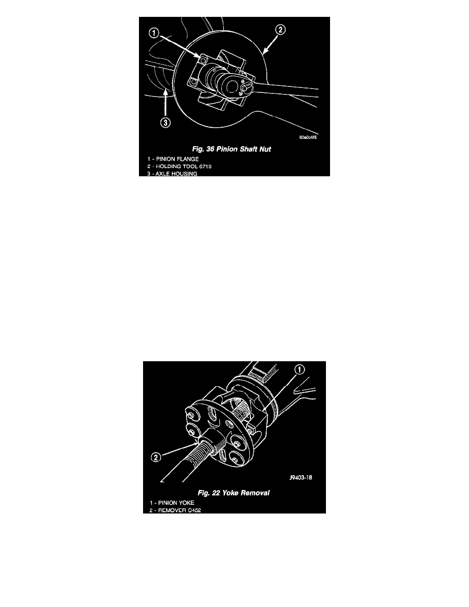
5. If the rotating torque is to low, use Holder 6719A to hold the pinion yoke (Fig. 36) and tighten the pinion shaft nut in 6.8 Nm (5 ft. lbs.) until
proper rotating torque is achieved.
6. Installation propeller shaft with reference marks aligned.
7. Check and add gear lubricant to axle if necessary.
8. Install brake rotors and calipers, refer to Brakes and Traction Control for procedure.
9. Install wheel and tire assemblies.
10. Lower the vehicle.
Rear Axle - 248RBI
REMOVAL
1. Raise and support the vehicle.
2. Scribe a mark on the universal joint, pinion yoke, and pinion shaft for reference.
3. Disconnect the propeller shaft from the pinion yoke. Secure the propeller shaft in an upright position to prevent damage to the rear universal joint.
4. Remove the wheel and tire assemblies.
5. Remove the brake drums to prevent any drag. The drag may cause a false bearing preload torque measurement.
6. Rotate the pinion yoke three or four times.
7. Measure the amount of torque necessary to rotate the pinion gear with a (inch lbs.) dial-type torque wrench. Record the torque reading for
installation reference.
8. Hold the yoke with Wrench 6719. Remove the pinion shaft nut and washer.
9. Remove the yoke with Remover C-452 (Fig. 22).
10. Remove the pinion shaft seal with suitable pry tool or slide-hammer mounted screw.
INSTALLATION
NOTE: The outer perimeter of the seal is pre-coated with a special sealant. An additional application of sealant is not required.