
RAM 2500 Truck 4WD L6-5.9L DSL Turbo VIN C (2004)
Inspect the connecting rod for damage and wear. The I-Beam section of the connecting rod cannot have dents or other damage. Damage to this part
can cause stress risers which will progress to breakage.
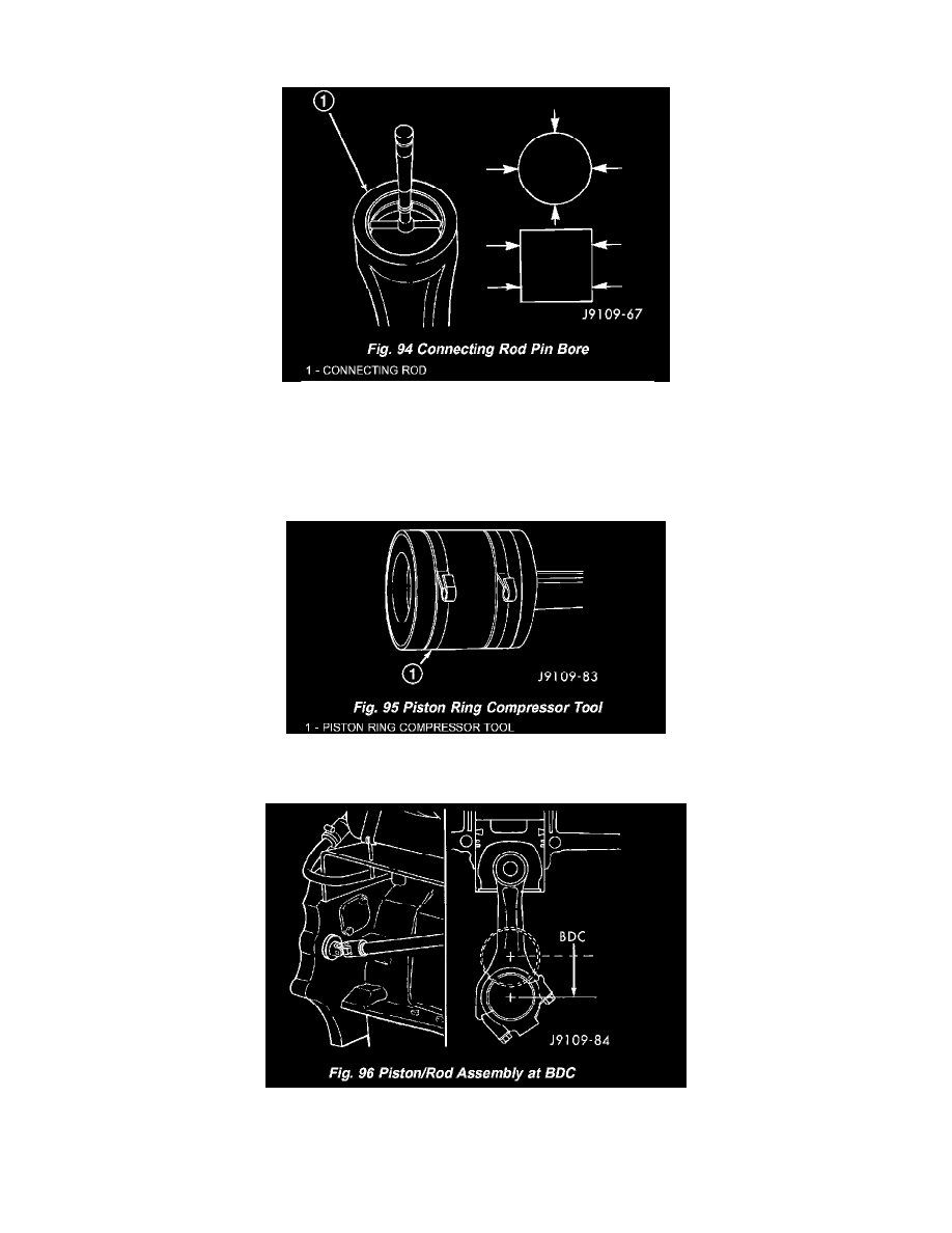
Measure the connecting rod pin bore (Fig. 94). The maximum diameter is 40.042 mm (1.5765 in.), minimum diameter is 40.019 mm (1.5756 in.). If
out of limits, replace the connecting rod.
INSTALLATION
1. Lubricate the cylinder bores with clean engine oil.
2. Generously lubricate the rings and piston skirts with clean engine oil.
3. Compress the rings using a piston ring compressor tool (Fig. 95). If using a strap-type ring compressor, make sure the inside end of the strap does
not hook on a ring gap and break the ring.
4. Bar the crankshaft so the rod journal for the piston to be installed is at BDC (Bottom Dead Center) - (Fig. 96).
5. Make sure the front of the piston is oriented properly according to the marking on the top of the piston and the numbers on the rod and cap are
oriented as illustrated.
6. Position the piston and rod assembly into the cylinder bore with the front of the piston oriented properly according to the stamping in the top of the
piston. In this position the numbers on the connecting rod should be facing the intake or camshaft side of the engine, and the rod bolt hex heads