
RAM 2500 Truck 4WD L6-6.7L DSL Turbo VIN A (2007)
IDENTIFICATION
In-line connectors are identified by a number, as follows:
-
In-line connectors located in the engine compartment are C100 series numbers.
-
In-line connectors located in the instrument panel area are C200 series numbers.
-
In-line connectors located in the body are C300 series numbers.
-
Jumper harness connectors are C400 series numbers.
-
Grounds and ground connectors are identified with a "G" and follow the same series numbering as the in-line connectors.
-
Splices are identified with an "S" and follow the same series numbering as the in-line connectors. In addition, S001-S099 numbers are located in
the engine compartment.
-
Component connectors are identified by the component name instead of a number. Multiple connectors on a component use a C1, C2, etc.
identifier.
LOCATIONS
The abbreviation T/O is used in the component location section to indicate a point in which the wiring harness branches out to a component. The
abbreviation N/S means Not Shown in the illustrations
Section Identification and Information
DESCRIPTION - SECTION IDENTIFICATION AND INFORMATION
The wiring diagrams are grouped into individual sections. If a component is most likely found in a particular group, it will be shown complete (all wires,
connectors, and pins) within that group. For example, the Auto Shutdown Relay is most likely to be found in Powertrain Management, so it is shown
there complete. It can, however, be shown partially in another group if it contains some associated wiring.
Splice diagrams show the entire splice and provide references to other sections the splices serves. Splice Information contains splice diagrams that are
not shown in their entirety somewhere else in the wiring diagrams.
Connector Pin-Outs shows each connector and the circuits involved with that connector. The connectors are identified using the name/number on the
diagram pages.
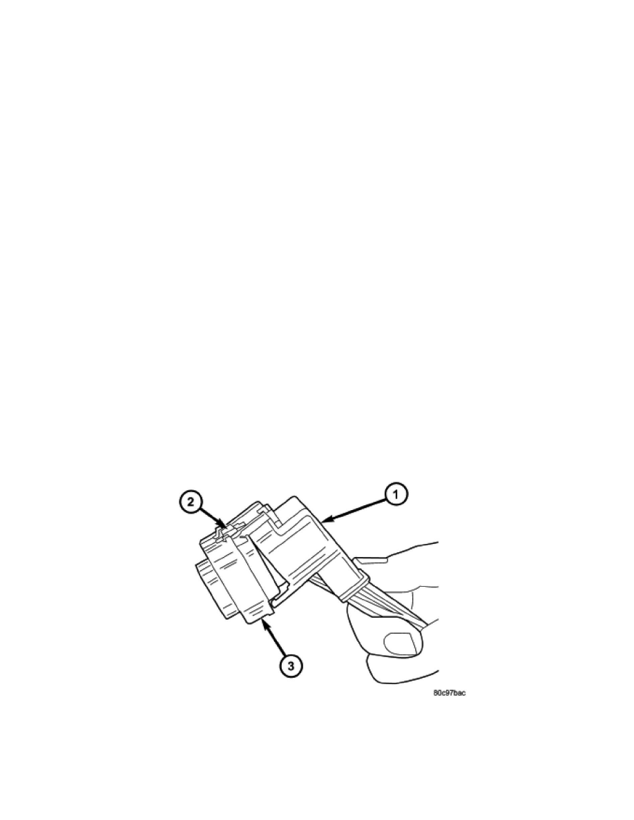
Removal
REMOVAL
1. Disconnect battery.
2. Release Connector Lock (2).
3. Disconnect the connector (3) being repaired from its mating half/component.
4. Remove the dress cover (if applicable) (1).