
RAM 2500 Truck 4WD V10-8.0L VIN W (1997)
Hydraulic Control Unit: Description and Operation
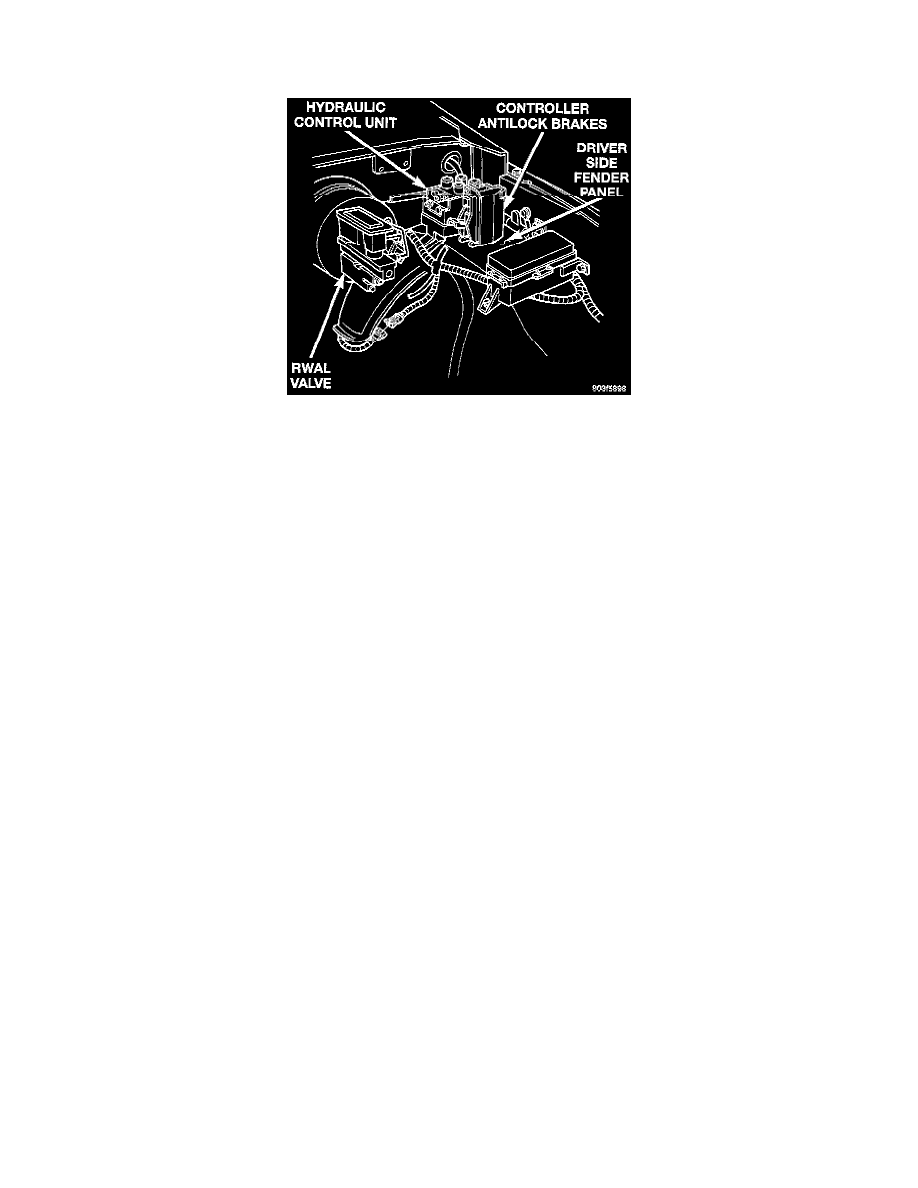
Hydraulic Control Unit (HCU)
Controller Antilock Brakes And Hydraulic Control Unit
GENERAL INFORMATION
The Hydraulic Control Unit (HCU) mounted on the driver side inner fender panel. The HCU consist of the front antilock valve assembly and
pump/motor unit.
FRONT ANTILOCK VALVE
The front brake antilock valve consists of a solenoid valve body. The antilock valve provides two channel pressure control of the front brakes. One
channel controls the left front brake unit. The second channel controls the right front brake unit. Each front brake unit is controlled independently.
The solenoid valves are cycled open and closed as needed during antilock braking. They are cycled rapidly and continuously to modulate brake
fluid pressure and control wheel lock-up and deceleration.
PUMP/MOTOR
The pump is run by a DC type motor controlled by the Controller Antilock Brake (CAB). The pump supplies the additional fluid volume needed
during antilock braking.
CIRCUIT OPERATION
Circuit B120 from the ABS pump relay supplies voltage for the ABS pump motor plus the isolation and dump solenoids in the hydraulic control
unit. The Controller Antilock Brake (CAB) activates the pump motor and the solenoids by providing separate ground paths for each.
The CAB provides a ground path for the motor on circuit B60. Circuit B60 connects to the CAB two-way connector.
The CAB cycles the isolation and dump solenoids in the front anti-lock valve by providing a ground path for each on separate circuits:
-
Circuit B248 connects to cavity 30 of the CAB and provides ground for the right front dump solenoid.
-
Circuit B249 connects to cavity 33 of the CAB and provides ground for the right front isolation solenoid.
-
Circuit B243 connects to cavity 35 of the CAB and provides ground for the left front dump solenoid.
-
Circuit B245 connects to cavity 37 of the CAB and provides ground for the left front isolation solenoid.
There are two reset switches in the hydraulic control unit; a left switch and a right switch, both provide inputs to the CAB. Circuit B5 from the left
reset switch connects to CAB cavity 5 while circuit B18 from the right reset switch connects to cavity 18.