
RAM 2500 Truck 4WD V10-8.0L VIN W (1997)
Manifold Pressure/Vacuum Sensor: Testing and Inspection
Sensor Test
Fig. 50 Map Sensor
To test the Manifold Absolute Pressure (MAP) sensor:
CAUTION: When testing the MAP sensor, be sure that the harness wires are not damaged by the test meter probes.
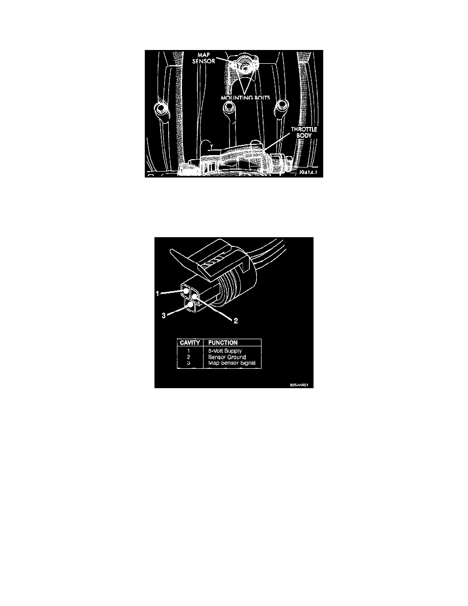
Fig. 61 Sensor Connector Terminals
1. Test the MAP sensor output voltage at the MAP sensor connector between terminals 1 and 3. With the ignition switch ON and the engine OFF,
output voltage should be 4-to-5 volts. The voltage should drop to 1.5-to-2.1 volts with a hot, neutral idle speed condition.
2. Test powertrain control module (PCM) cavity A-27 for the same voltage described above to verify the wire harness condition. Repair as
necessary.
3. Test MAP sensor supply voltage at sensor connector between terminals 1 and 2 with the ignition ON. The voltage should be approximately 5 volts
(+/-0.5V). Five volts (+/-O.5V) should also be at cavity A-17 of the PCM wire harness connector. Repair or replace the wire harness as necessary.
4. Test the MAP sensor ground circuit at sensor connector terminal-2 and PCM connector A-4. Repair the wire harness if necessary