
RAM 2500 Truck 4WD V10-8.0L VIN W HDC (2000)
Heated Element: Description and Operation
Heated Mirror Switch
HEATED MIRROR SWITCH
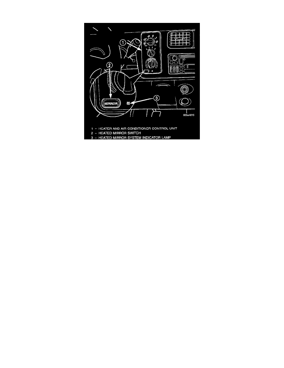
The heated mirror switch, the heated mirror system indicator lamp, the heated mirror system solid state electronic control logic and timer circuitry
and the heated mirror relay are all integral to the heater and air conditioner control unit, which is located between the instrument cluster and the
radio near the center of the instrument cluster bezel on the instrument panel. The heated mirror switch and the heated mirror system indicator lamp
are visible in the lower left corner of the heater and air conditioner control unit face plate. The solid state electronic control logic and timer
circuitry and the heated mirror relay are not visible, but are also located within the housing of the heater and air conditioner control unit.
The heated mirror switch, the heated mirror system indicator lamp, the heated mirror system solid state electronic control logic and timer circuitry
and the heated mirror relay cannot be repaired. If any of these components is damaged or faulty, the entire heater and air conditioner control unit
must be replaced. Refer to Heater-A/C Control for the location of the proper heater and air conditioner control removal and installation
procedures.
The momentary-type heated mirror switch provides a hard-wired battery current signal to the heated mirror system electronic control logic
circuitry each time it is depressed. In response to the heated mirror switch input, the electronic control logic and timer circuitry energizes or
de-energizes the amber heated mirror system indicator lamp next to the heated mirror switch to indicate that the heated mirror system is turned ON
or OFF. The electronic control logic and timer circuitry also energizes or de-energizes the heated mirror relay, which controls the feed of electrical
current to the outside mirror heating grids.
The heated mirror system electronic control logic and timer circuitry is programmed to turn the heated mirror system Off automatically after about
15 minutes of operation. If the heated mirror system is turned On a second time following an initial time-out event during the same ignition switch
cycle, the heated mirror system electronic control logic and timer circuit is programmed to turn the system Off automatically after about five
minutes. When the electronic control logic and timer circuit detects that a programmed time interval has elapsed, it will automatically de-energize
the heated mirror system indicator lamp and the heated mirror relay. The heated mirror system will also be turned OFF if the heated mirror switch
is depressed while the system is turned ON, or if the ignition switch is turned to the OFF or ACCESSORY positions.
OUTSIDE MIRROR HEATING GRID
Vehicles equipped with the optional heated mirror system have an electrically operated heating grid located behind the mirror glass of each power
operated outside rear view mirror. The outside mirror heating grid consists of two thin laminations of plastic that approximate the outer dimensions
and shape of the mirror glass. A single length of resistor wire weaves in a back and forth pattern between, and is held in place by the two thin
laminations of plastic. The two ends of the resistor wire terminate near the inboard edge of the grid, where they are soldered to the ground feed and
battery current feed wires contained in the power mirror wire harness. The heating grid is then sandwiched between the back of the molded plastic
mirror glass case and the mirror glass, where it remains in direct contact with the back of the mirror glass at all times.
The outside mirror heating grids cannot be repaired and, if faulty or damaged, the entire outside power mirror unit must be replaced. Refer to
Power Mirror for the location of the proper power mirror unit removal and installation procedures.
One end of the outside mirror heating grid resistor wire is connected to a ground feed at all times through a body ground screw located inside the
left rear corner of the truck cab. Battery current is directed to the other end of the outside mirror heating grid resistor wire by the energized heated