
RAM 2500 Truck 4WD V10-8.0L VIN W HDC (2000)
Seals and Gaskets: Service and Repair
Rear Axle - 9 1/4
REMOVAL
1. Raise and support the vehicle.
2. Scribe a mark on the universal joint, companion flange, and pinion shaft for installation reference.
3. Disconnect the propeller shaft from the companion flange. Secure the propeller shaft in an upright position to prevent damage to the rear universal
joint.
4. Remove the wheel and tire assemblies.
5. Remove the brake drums to prevent any drag. The drag may cause a false bearing preload torque measurement.
6. Rotate the companion flange three or four times.
7. Measure the amount of torque necessary to rotate the pinion with a (inch lbs.) dial-type torque wrench. Record the torque reading for installation
reference.
8. Install socket head bolts into two of the threaded holes in the companion flange, 180° apart.
9. Position Holder 6719 against the companion flange and install a hex head bolt and washer into one of the remaining threaded holes. Tighten the
bolt and washer so that the Holder 6719 is held to the flange.
10. Hold the flange with Holder 6719. Remove the pinion nut and washer.
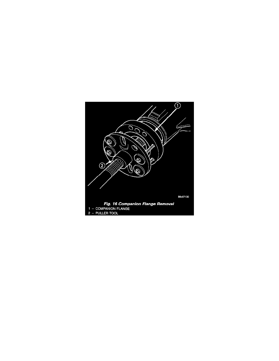
Fig. 16
11. Remove the companion flange with Remover C-452 (Fig. 16).
12. Remove the pinion seal with suitable pry tool or slide-hammer mounted screw.
INSTALLATION
1. Clean the seal contact surface in the housing bore.
2. Examine the splines on the pinion shaft for burrs or wear. Remove any burrs and clean the shaft.
3. Inspect companion flange for cracks, worn splines and worn seal contact surface. Replace companion flange if necessary.
NOTE: The outer perimeter of the seal is pre-coated with a special sealant. An additional application of sealant is not required.
4. Apply a light coating of gear lubricant on the lip of pinion seal.
5. Install the new pinion seal with Installer C-3860-A and Handle C-4171.
NOTE: The seal is correctly installed when the seal flange contacts the face of the differential housing.
6. Position the companion flange on the end of the shaft with the reference marks aligned.
7. Install socket head bolts into two of the threaded holes in the companion flange, 1800 apart.
8. Position Holder 6719 against the companion flange and install a hex head bolt and washer into one of the remaining threaded holes. Tighten the
bolt and washer so that the Holder 6719 is held to the flange.
9. Seat companion flange on pinion shaft with Installer C-3718 and Holder 6719.
10. Remove the Installer C-3718 and install the pinion washer and a new pinion nut. The convex side of the washer must face outward.
CAUTION: Do not exceed the minimum tightening torque when installing the companion flange retaining nut at this point. Damage to