
RAM 2500 Van V8-318 5.2L VIN T Magnum CNG SFI (1997)
Check the clutch pulley hub bearing for roughness or excessive leakage of grease. Check for bearing grease contamination on the armature plate
faces. Replace the bearing, if required.
CAUTION: The pulley and clutch plate were mated at the factory by a burnishing operation. No attempt should be made to separately replace either
part. This will result in clutch slippage due to insufficient contact area.
INSTALLATION
1. Position the back of the clutch field coil on the compressor front cover. Be sure the locating pin on the back of the coil lines up with the
indentation on the compressor front cover. This ensures the correct orientation of the coil and the wire harness.
2. Route the coil wire harness through the clamps on the compressor front cover and secure. Plug in the thermal limiter switch wire harness
connectors.
3. Install the field coil retaining snap ring (bevel side outward) with snap ring pliers. Be certain that the snap ring is properly seated into the groove.
CAUTION: If the snap rings on the field coil or the pulley assembly are not fully seated, they will vibrate out. A clutch failure and damage to the
compressor may result.
4. Position the pulley assembly onto the compressor.
CAUTION: Do not mar the pulley friction surface.
5. Install the pulley assembly retaining snap ring (bevel side outward) with snap ring pliers. Be certain that the snap ring is properly seated in the
groove.
6. Place a trial stack of shims, 2.54 mm (0.10 in.) thick, on the compressor shaft.
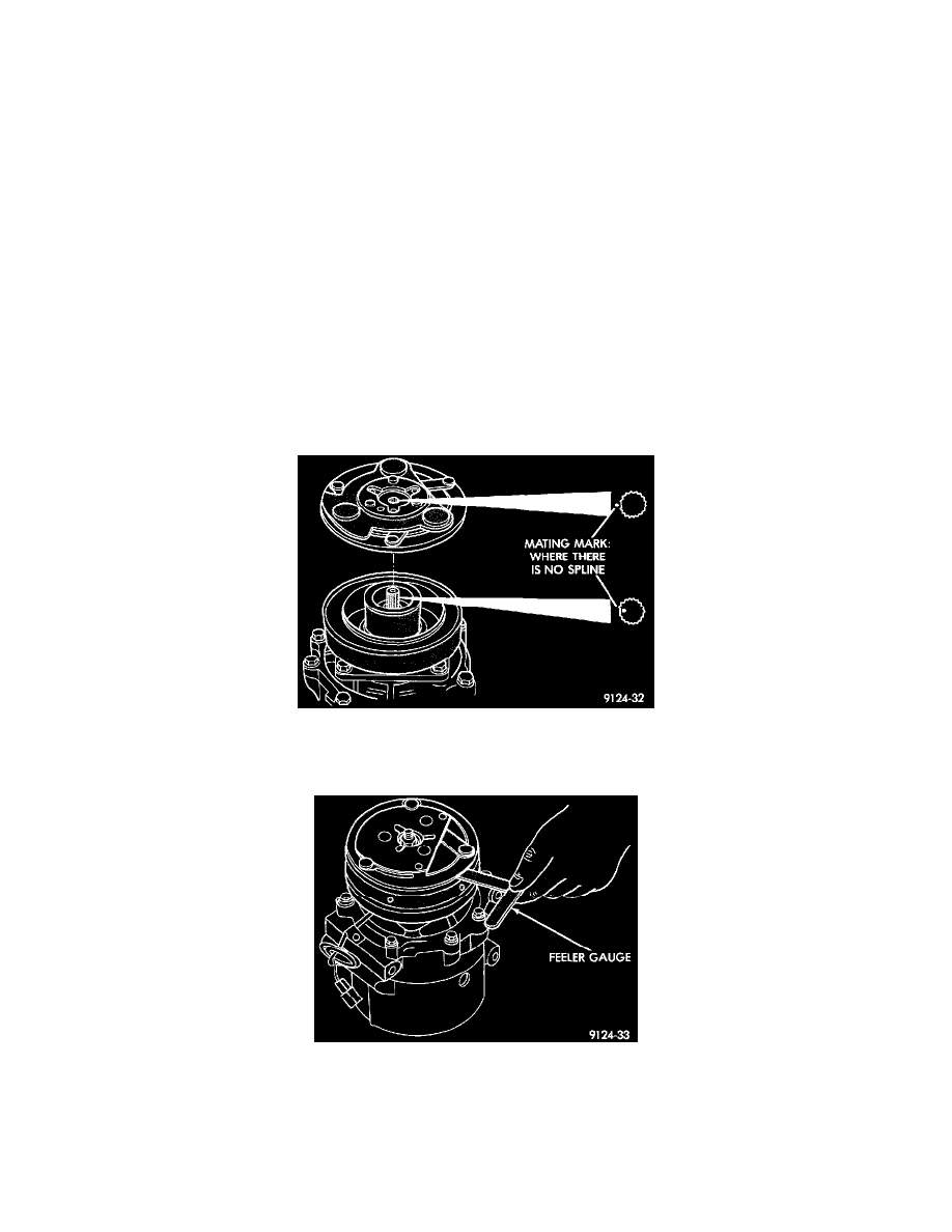
Fig 17 Aligning Clutch Plate Splines
7. Install the clutch plate on the compressor shaft. Note the machined mating splines.
Fig 18 Check Clutch Air Gap
8. With the front clutch plate assembly tight against the shims, measure the air gap between the clutch plate and the pulley face with a feeler gauge.
The air gap should be between 0.35 and 0.65 mm (0.013 and 0.025 inch). If the proper air gap is not obtained, add or subtract shims until the
desired air gap is obtained.
9. Install the compressor shaft nut. Tighten the nut to 14.4 N.m (10.5 ft. lbs.).
10. The shims may compress after tightening the shaft nut. Check the air gap in four or more places to verify that the air gap is still correct. Spin the