
RAM 2500 Van V8-318 5.2L VIN T Magnum CNG SFI (1997)
Air Bag Control Module: Service and Repair
WARNING:
^
The airbag control module contains the impact sensor, which enables the system to deploy the airbag and seat belt pre-tensioner. To
avoid accidental deployment, never connect the airbag control module electrically to the system unless it is bolted to the vehicle. Never
strike or kick the airbag control module. Before beginning any airbag system removal or installation procedures, disconnect and isolate
the battery negative (ground) cable from the vehicle battery. Then wait two minutes for the system capacitor to discharge before further
system service. This is the only sure way to disable the airbag system. Failure to do this could result in accidental air bag system
deployment, and possible personal injury.
^
The airbag control module must never be relocated from its factory-in- stalled position. The plastic air bag control module protective
cover must always be reinstalled following any service removal. Care should be exercised to protect the airbag control module from direct
spray or submersion in water or other liquids. Never strike the airbag control module with tools or other objects. Never stand on or place
objects on the airbag control module. Failure to heed these warnings could result in accidental airbag system deployment, or non-
deployment of the airbag system when needed, and possible personal injury.
1. If so equipped, adjust the power seat to the full forward and full upward position.
2. Disconnect and isolate the battery negative cable. If the airbag system is undeployed, wait two minutes for the system capacitor to discharge before
further service.
3. Unplug the wire harness connectors for the seat belt switch and, if so equipped, the power seat adjuster.
4. Remove the four rearward facing fasteners that secure the seat riser rear shield to the seat riser and lift the shield to access the seat riser rear
mounting nuts.
5. Remove the four nuts that secure the driver seat riser to the floor panel.
6. Remove the driver seat and riser as an assembly
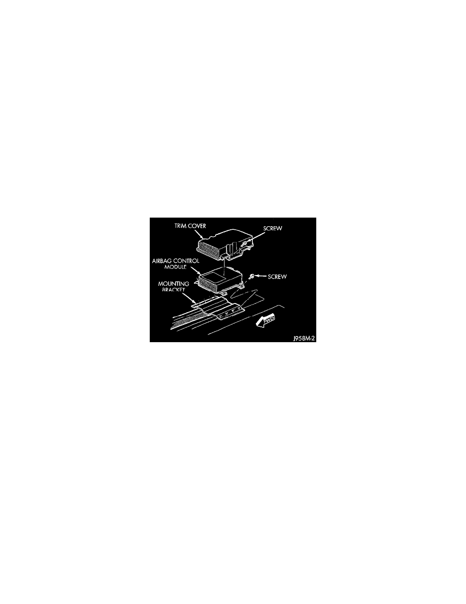
7. Remove the four screws that secure the ACM trim cover and remove the cover.
8. Unplug the two wire harness connectors from the rear of the ACM.
9. Remove the four screws that secure the ACM to the mounting bracket and remove the ACM.
10. Reverse the removal procedures to install. Be certain that the arrow on the ACM housing is oriented towards the front of the vehicle, and that the
wire harness is correctly routed through the trough formation in the ACM mounting bracket. Tighten the ACM screws to 7.5 N.m (65 in. lbs.). Do
not connect the battery negative cable at this time. See Testing and Inspection/Procedures for the proper procedures.