
RAM 2500 Van V8-5.2L Prop VIN 2 (2000)
Fuse Block: Description and Operation
FUSEBLOCK MODULE
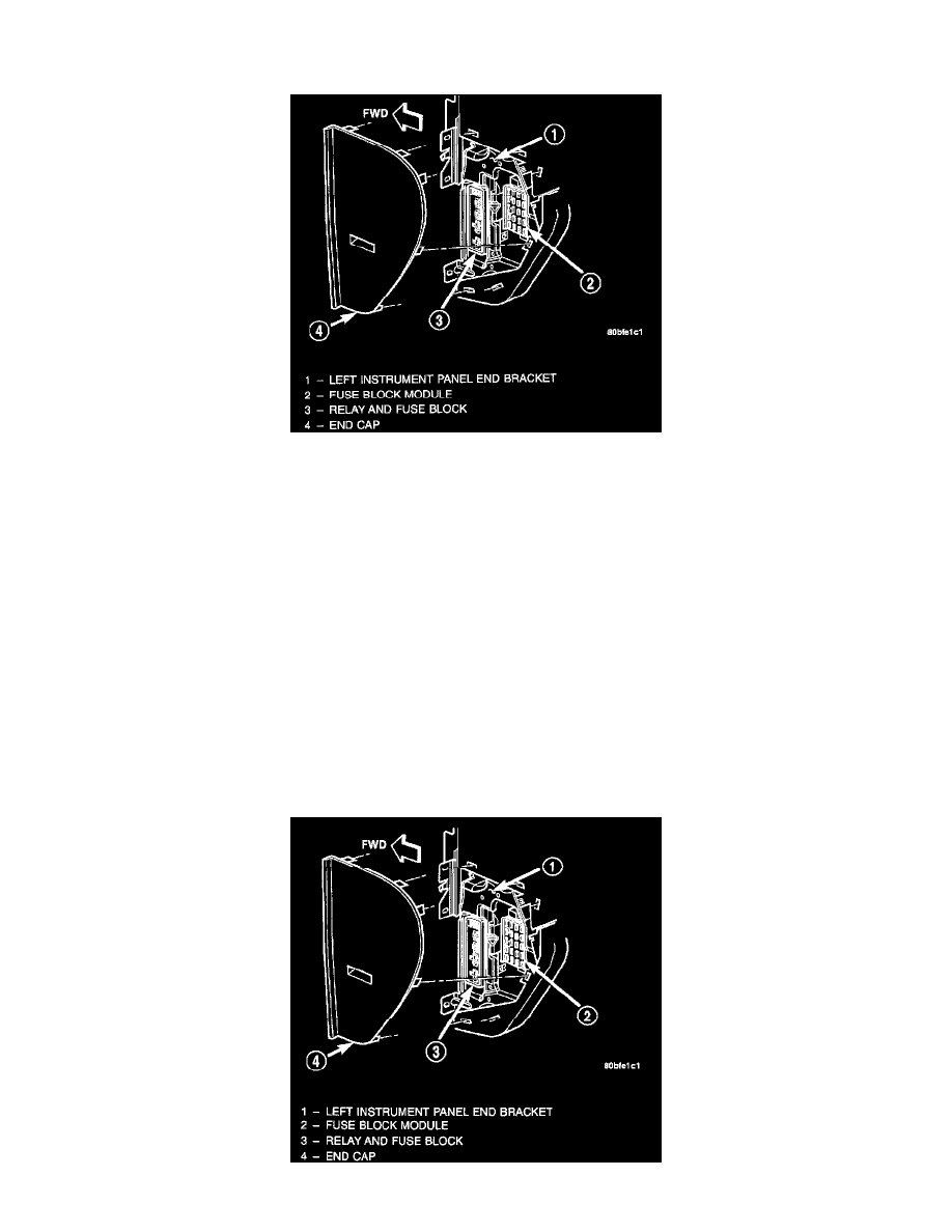
Fuseblock Module Location
An electrical fuseblock module is concealed behind the driver side instrument panel end cap, just rearward of the relay and fuse block. The
fuseblock module serves to distribute electrical current to many of the accessory systems in the vehicle. The fuseblock module houses up to twenty
blade-type mini fuses, up to two blade-type automatic resetting circuit breakers and an International Standards Organization (ISO) relay.
Additional provisions are available in the fuseblock module for a second ISO relay and an ignition lamp time delay relay; however, these
provisions are not used in this vehicle application.
The molded plastic fuseblock module housing has an integral mounting bracket that is secured with two screws to the left instrument panel end
bracket. The driver side instrument panel end cap also serves as a snap-fit fuse access panel that can be removed for service of the fuseblock
module and the relay and fuse block. A finger recess is molded into the end cap for easy removal. A fuse layout map is molded onto the back side
of the end cap to ensure proper fuse identification.
The fuseblock module is integral to the instrument panel wire harness. If any internal circuit or the fuseblock module housing is faulty or damaged,
the entire fuseblock module and instrument panel wire harness unit must be replaced.
All of the circuits entering and leaving the fuse- block module do so through the instrument panel wire harness. Internal connection of all of the
fuse- block module circuits is accomplished by an intricate combination of hard wiring and bus bars.
RELAY AND FUSE BLOCK