
RAM 2500 Van V8-5.2L Prop VIN 2 (2000)
Wiper Relay: Testing and Inspection
The intermittent wipe relay is used on vehicles that are equipped with the Vehicle Theft Security System (VTSS). If the problem being diagnosed
involves only some of the intermittent wipe delay positions, see Wiper Switch and Washer Switch. If the problem being diagnosed involves all of the
intermittent wipe delay positions, proceed with the following tests.
WARNING: ON VEHICLES EQUIPPED WITH AIR- BAGS, REFER TO AIRBAGS AND SEAT BELTS/AIRBAGS BEFORE
ATTEMPTING ANY STEERING WHEEL, STEERING COLUMN, OR INSTRUMENT PANEL COMPONENT DIAGNOSIS OR SERVICE.
FAILURE TO TAKE THE PROPER PRECAUTIONS COULD RESULT IN ACCIDENTAL AIRBAG DEPLOYMENT AND POSSIBLE
PERSONAL INJURY.
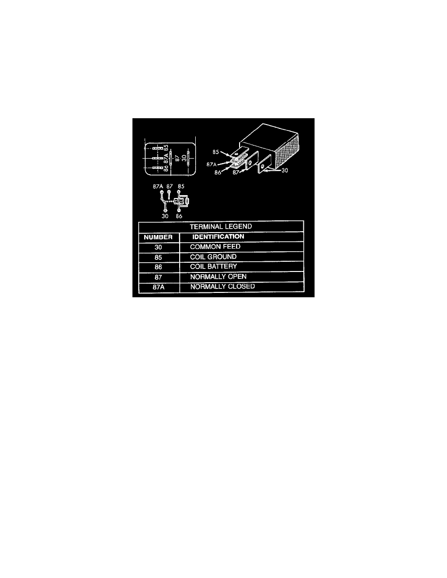
RELAY TEST
Intermittent Wipe Relay
The intermittent wipe relay is located in a connector that is taped back to the instrument panel wire harness above the inboard side of the glove box
opening in the passenger compartment. Remove the intermittent wipe relay from its wire harness connector as described to perform the following tests:
1. A relay in the de-energized position should have continuity between terminals 87A and 30, and no continuity between terminals 87 and 30. If OK,
go to Step 2. If not OK, replace the faulty relay.
2. Resistance between terminals 85 and 86 (electromagnet) should be 75 ± 5 ohms. If OK, go to Step 3. If not OK, replace the faulty relay.
3. Connect a battery to terminals 85 and 86. There should now be continuity between terminals 30 and 87, and no continuity between terminals 87A
and 30. If OK, see Relay Circuit Test. If not OK, replace the faulty relay.
RELAY CIRCUIT TEST
1. The relay common feed terminal cavity (30) is connected to the wiper (multi-function) switch. There should be continuity between the cavity for
relay terminal 30 and the two washer switch output (V11a and V11B) circuit cavities in the instrument panel half of the steering column wire
harness connector at all times. If OK, go to Step 2. If not OK, repair the open circuit(s) to the wiper (multi-function) switch as required.
2. The relay normally closed terminal (87A) is connected to terminal 30 in the de-energized position. There should be continuity between the cavity
for relay terminal 87A and the wiper park switch sense circuit cavities of the wiper motor wire harness connector and the 14-way Central Timer
Module (CTM) wire harness connector at all times. If OK, go to Step 3. If not OK, repair the open circuit(s) to the wiper motor and CTM as
required.
3. The relay normally open terminal (87) is connected to the common feed terminal (30) in the energized position. There should be battery voltage at
the cavity for relay terminal 87 with the ignition switch in the ON or Accessory positions. If OK, go to Step 4. If not OK, repair the open circuit to
the fuse in the fuseblock module as required.
4. The coil battery terminal (86) is connected to the electromagnet in the relay. There should be battery voltage at the cavity for relay terminal 86
with the ignition switch in the ON or Accessory positions. If OK, go to Step 5. If not OK, repair the open circuit to the fuse in the fuseblock
module as required.
5. The coil ground terminal (85) is connected to the electromagnet in the relay. It is grounded by the CTM to energize the relay and cycle the wiper
motor. Check for continuity between the cavity for relay terminal 85 and the intermittent wiper relay control circuit cavity of the 14-way CTM
wire harness connector. There should be continuity. If OK, use a DRB scan tool and the proper Diagnostic Procedures for diagnosis of the CTM.
If not OK, repair the open circuit to the CTM as required.