
RAM 2500 Van V8-5.2L Prop VIN 2 (2000)
Drive/Propeller Shaft: Service and Repair
Service Procedures
Driveline Angle Measurement Preparation
Before measuring universal joint angles, the following must be done;
^
Inflate all tires to correct pressure.
^
Check the angles in the same loaded or unloaded condition as when the vibration occurred. Propeller shaft angles change according to the amount
of load in the vehicle.
^
Check the condition of all suspension components and verify all fasteners are torqued to specifications.
^
Check the condition of the engine and transmission mounts and verify all fasteners are torqued to specifications.
Propeller Shaft Angle Measurement
NOTE: The following procedure is depicted using an axle equipped with a pinion yoke. The procedure and principles are the same for axles equipped
with a companion flange.
ONE-PIECE PROPELLER SHAFT
To accurately check driveline alignment, raise and support the vehicle at the axles as level as possible. Allow the wheels and propeller shaft to turn.
Remove any external bearing snap rings (if equipped) from universal joint so that the inclinometer base sits flat.
1. Rotate the shaft until transmission/transfer case output yoke bearing cap is facing downward.
Always make measurements from front to rear.
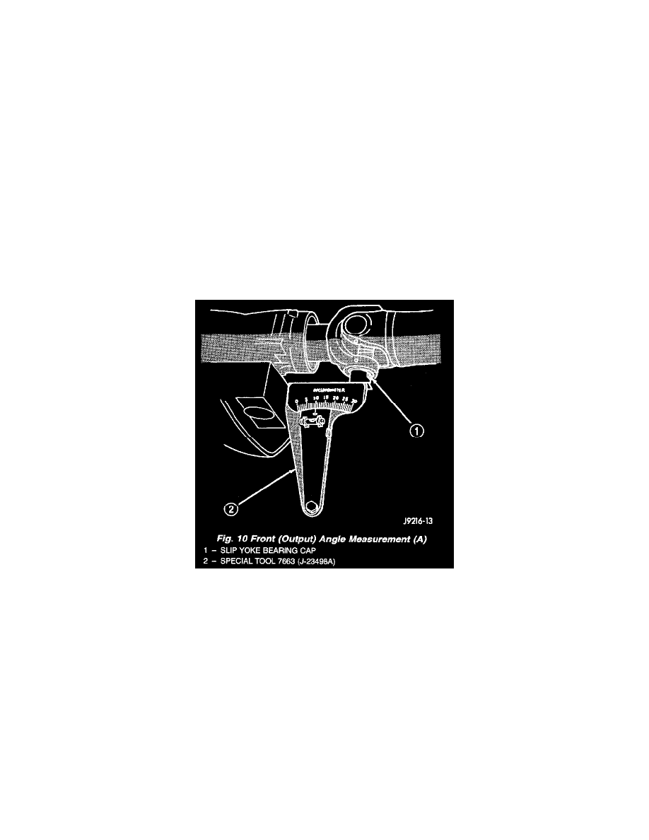
Fig. 10
2. Place Inclinometer on yoke bearing cap (A) parallel to the shaft (Fig. 10). Center bubble in sight glass and record measurement.
This measurement will give you the transmission or Output Yoke Angle (A).