
RAM 2500 Van V8-5.2L VIN Y (1998)
Horn Relay: Testing and Inspection
WARNING: ON VEHICLES EQUIPPED WITH AIRBAGS, REFER TO AIRBAGS BEFORE ATTEMPTING ANY STEERING WHEEL,
STEERING COLUMN, OR INSTRUMENT PANEL COMPONENT DIAGNOSIS OR SERVICE. FAILURE TO TAKE THE PROPER
PRECAUTIONS COULD RESULT IN ACCIDENTAL AIRBAG DEPLOYMENT AND POSSIBLE PERSONAL INJURY.
Relay Test
Horn Relay
The horn relay is located in the junction block in the passenger compartment. Remove the horn relay from the junction block to perform the following
tests:
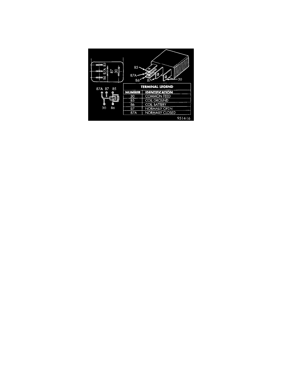
1. A relay in the de-energized position should have continuity between terminals 87A and 30, and no continuity between terminals 87 and 30. if OK,
go to Step 3. If not OK, replace the faulty relay.
2. Resistance between terminals 85 and 86 electromagnet. should be 75 - 5 Ohms. If OK, go to Step 4. If not OK, replace the faulty relay.
3. Connect a battery to terminals 85 and 86. There should now be continuity between terminals 30 and 87, and no continuity between terminals 87A
and 30. If OK, see Relay Circuit Test in the Diagnosis and Testing. If not OK, replace the faulty relay.
Relay Circuit Test
1. The relay common feed terminal cavity 30. is connected to battery voltage and should be hot at all times. If OK, go to Step 3. If not OK, repair the
open circuit to the PDC fuse as required.
2. The relay normally closed terminal 87A. is connected to terminal 30 in the de-energized position, but is not used for this application. Go to Step 4.
3. The relay normally open terminal 87. is connected to the common feed terminal 30. in the energized position. This terminal supplies battery
voltage to the horns. There should be continuity between the cavity for relay terminal 87 and the horn relay output circuit cavity of each horn wire
harness connector at all times. If OK, go to Step 5. If not OK, repair the open circuit to the horns. as required.
4. The coil battery terminal 86. is connected to the electromagnet in the relay. It is connected to battery voltage and should be hot at all times. Check
for battery voltage at the cavity for relay terminal 86. If OK, go to Step 6. If not OK, repair the open circuit to the fuse in the PDC as required.
5. The coil ground terminal 85. is connected to the electromagnet in the relay It is grounded through the horn switch when the horn switch is
depressed. On vehicles equipped with the Vehicle Theft Security System VTSS., the horn relay coil ground terminal can also be grounded by the
Central Timer Module CTM. in response to certain inputs related to the VTSS or Remote Keyless Entry (RKE). system. Check for continuity to
ground at the cavity for relay terminal 85. There should be continuity with the horn switch depressed, and no continuity with the horn switch
released. If not OK, see Horn Switch in the Diagnosis and Testing.
WARNING: ON VEHICLES EQUIPPED WITH AIRBAGS, REFER TO AIRBAGS BEFORE ATTEMPTING ANY STEERING WHEEL,
STEERING COLUMN, OR INSTRUMENT PANEL COMPONENT DIAGNOSIS OR SERVICE. FAILURE TO TAKE THE PROPER
PRECAUTIONS COULD RESULT IN ACCIDENTAL AIRBAG DEPLOYMENT AND POSSIBLE PERSONAL INJURY.
The horn relay is located in the junction block in the passenger compartment. Remove the horn relay from the junction block to perform the following
tests:
1. A relay in the de-energized position should have continuity between terminals 87A and 30, and no continuity between terminals 87 and 30. If OK,
go to Step 3. If not OK, replace the faulty relay.
2. Resistance between terminals 85 and 86 (electromagnet) should be 75 ± 5 ohms. If OK, go to Step 4. If not OK, replace the faulty relay.
3. Connect a battery to terminals 85 and 86. There should now be continuity between terminals 30 and 87, and no continuity between terminals 87A
and 30. If OK, test the relay circuits. If not OK, replace the faulty relay.