
RAM 2500 Van V8-5.2L VIN Y (1998)
^
WHEEL BEARING ADJUSTMENT
1.
Verify the front wheel bearing end play. If the end play is above the specification, complete the following repair procedure
NOTE:
The end play should be 0.25-0.076 mm (0.001-0.003 in.).
2.
Remove the dust cover, nut lock and cotter pin. Tighten the nut to 54 N.m (40 ft. lb. to preload the bearing while rotating the hub/rotor. Stop
hub/rotor and loosen the nut to completely release bearing preload torque. Tighten the nut to 3 N.m (25 in. lb.). Install the nut lock and a new
cotter pin.
3.
Clean the dust cap and apply a coating lubricant to the internal surface. Do not fill the dust cap with lubricant. Install the cap.
STEERING GEAR REPLACEMENT
NOTE:
INSPECT THE BAR CODE LABEL ON THE STEERING GEAR AND NOTE THE PART NUMBER. IF THE PART NUMBER IS 52039231
AD OR 52039231AE (14:1 RATIO) THE VEHICLE WILL REQUIRE STEERING GEAR REPLACEMENT. IF THE PART NUMBER IS
52039231AB OR 52039231AC (16-13:1 VARIABLE RATIO), STEERING GEAR REPLACEMENT IS NOT REQUIRED. MOST 1998 AND
SOME EARLY 1999 VEHICLES WILL BE EQUIPPED WITH THE 16-13 :1 VARIABLE RATIO GEAR.
1.
Using the procedures outlined in the appropriate service manual, remove the steering gear and install the new steering gear, P/N 52013456AA.
NOTE:
MAKE SURE TO FILL THE STEERING SYSTEM WITH FLUID (P/N 04883077) AND PURGE ALL AIR FROM THE SYSTEM AS
OUTLINED IN THE APPROPRIATE SERVICE MANUAL.
^
REAR SPRINGS AND SHOCK ABSORBERS REPLACEMENT (8700 LB. GVW ONLY)
NOTE:
THE REAR SPRINGS AND SHOCK ABSORBERS ON THE 8700 LB. GVW VEHICLES WILL REQUIRE UPGRADING TO THE
COMPONENTS USED ON THE 9200 LB. GVW VEHICLES. INSTALLATION OF THE UPGRADED SPRINGS AND SHOCKS IS NOT
REQUIRED ON 9200 LB. GVW VEHICLES. FOR 9200 LB. GVW VEHICLES, PROCEED TO THE WHEEL ALIGNMENT.
CAUTION:
THE REAR OF THE VEHICLE MUST BE LIFTED USING A HOIST. THE LIFT MUST BE PLACED UNDER THE FRAME RAIL
CROSSMEMBER LOCATED AFT OF THE REAR AXLE. USE CARE TO AVOID BENDING THE SIDE RAIL FLANGE.
1.
Raise the vehicle on a hoist and inspect the rear springs and shock absorbers. The heavy duty spring part number is **52106156AD**. The heavy
duty shock part number is **52106320AC**. It the part numbers on the components differ from these numbers, they must be replaced.
2.
Using the procedures outlined in the appropriate service manual, remove the rear springs and shock absorbers. Install new springs, p/n
**52106156AD** and new shock absorbers, p/n **52106320A0 **
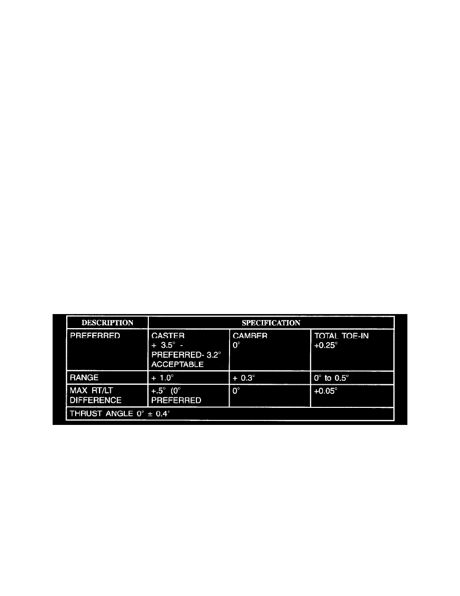
WHEEL ALIGNMENT
NOTE:
IF THE VEHICLE IS EQUIPPED WITH A REAR SUSPENSION AIR LEVELING SYSTEM, ENSURE THAT THE SYSTEM IS DEFLATED
PRIOR TO PERFORMING A WHEEL ALIGNMENT.