
RAM 2500 Van V8-5.2L VIN Y (1998)
23. Position adjusting screw bracket on valve body. Align valve springs and press bracket into place. Install short, upper bracket screws first and long
bottom screw last. Verify that valve springs and bracket are properly aligned. Then tighten all three bracket screws to 4 Nm (35 inch lbs.) torque.
24. Install module and connecting tube. Be sure long end of tube goes to module. Tighten module screws to 4 Nm (35 inch lbs.) torque.
25. Install throttle lever in valve body. Then install manual lever over throttle lever and start manual lever into valve body.
26. Align manual lever detent with detent ball and align lever arm with manual valve. Hold throttle lever upward. Then press down on manual lever
until lever is fully seated.
27. Install manual lever seal, washer and retaining E-clip.
28. Lubricate shaft of manual lever with light coat of petroleum jelly. This will help protect seal lip when manual shaft seal is installed.
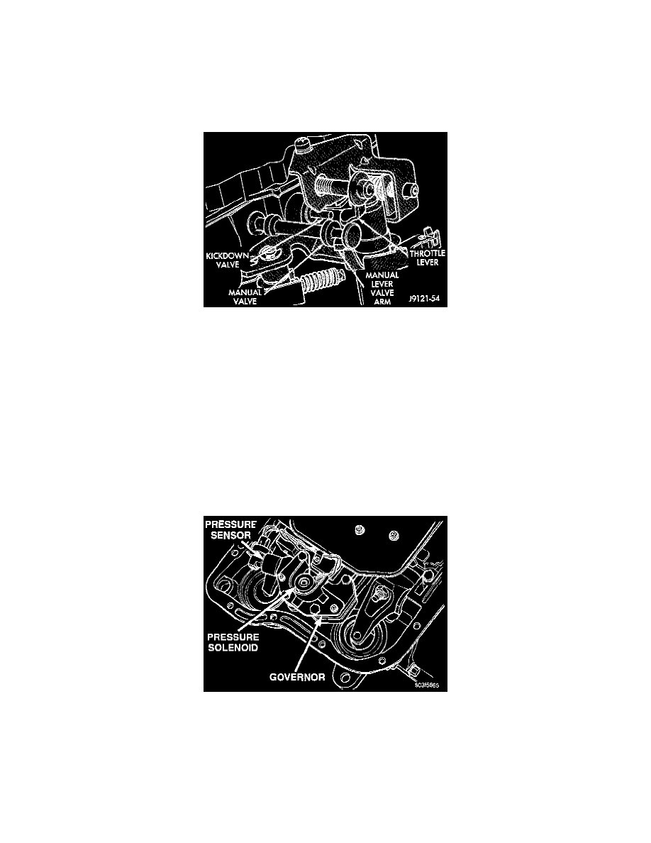
Manual And Throttle Lever Alignment
29. Verify that throttle lever is aligned with end of kickdown valve stem and that manual lever arm is engaged in manual valve.
30. If line pressure and/or throttle pressure adjustment screw settings were not disturbed, continue with overhaul or reassembly. However, if
adjustment screw settings were moved or changed, re-adjust as described in Valve Body Control Pressure Adjustment procedure.
46RE (A518) 4-Speed
DISASSEMBLY
CAUTION: Do not clamp any valve body, component in a vise. This practice can damage the component resulting in unsatisfactory operation after
assembly and installation. Do not use pliers to remove any of the valves, plugs or springs and do not force any of the components out or into place.
The valves and valve body housings will be damaged if force is used. Tag or mark the valve body springs for reference as they are removed. Do not
allow them to become intermixed.
1. Remove fluid filter.
Governor Pressure Solenoid And Sensor Wire Locations
2. Disconnect wires from governor pressure sensor and solenoid.