
RAM 2500 Van V8-5.2L VIN Y (1998)
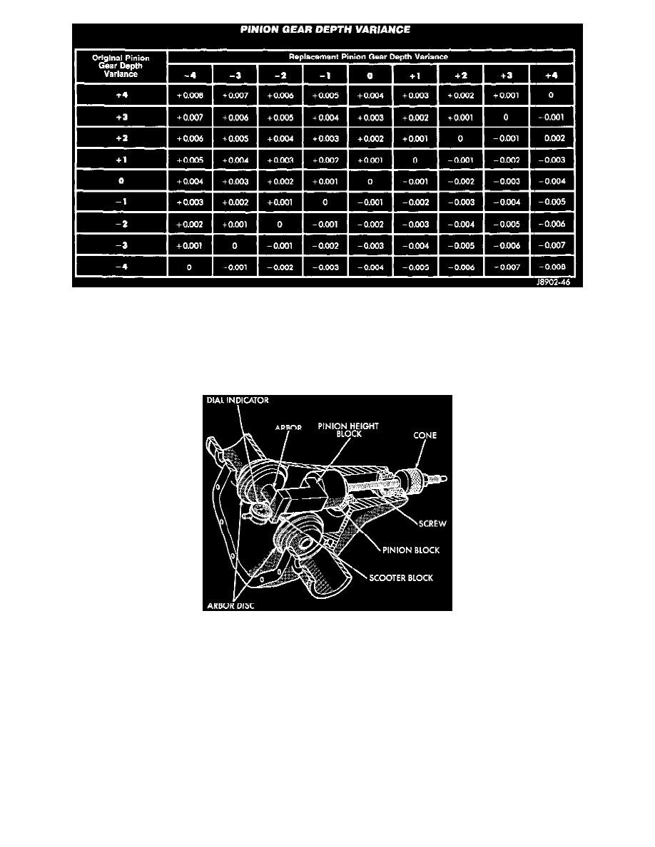
Note where Old and New Pinion Marking columns intersect. Intersecting figure represents plus or minus amount needed.
Note the etched number on the face of the drive pinion gear (-1, -2, 0, +1, +2, etc.). The numbers represent thousands of an inch deviation from the
standard. If the number is negative, add that value to the required thickness of the depth shim(s). If the number is positive, subtract that value from the
thickness of the depth shim(s). If the number is 0 no change is necessary. Refer to the Pinion Gear Depth Variance Chart.
PINION DEPTH MEASUREMENT AND ADJUSTMENT
Pinion Gear Depth Gauge Tools-Typical
Measurements are taken with pinion cups and pinion bearings installed in housing. Take measurements with a Pinion Gauge Set 6730 and Dial
Indicator C-3339.
1. Assemble Pinion Height Block 6739, Pinion Block 6736, and rear pinion bearing onto Screw 6741.