
RAM 2500 Van V8-5.9L VIN Z (1997)
Expansion Valve: Testing and Inspection
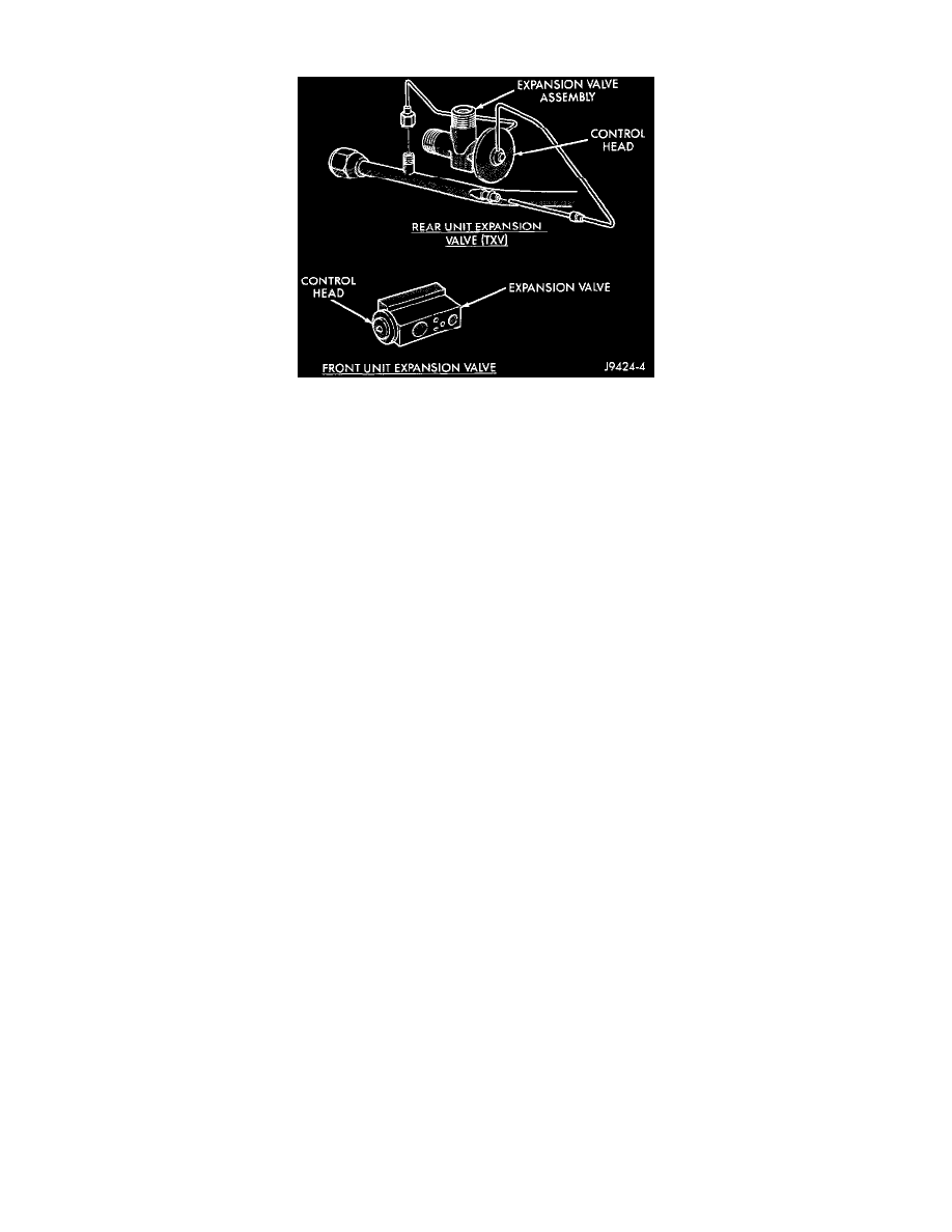
Fig 12 Expansion Valves
Tests must be made at an ambient temperature of 21 to 29°C (70 to 85°F).
FRONT A/C (ONLY)
1. Close the vehicle doors and windows, start the engine, and hold the engine speed at 1,000 rpm. Set the beater-A/C mode control switch to the Max
(A/C) position, the blower motor switch in the High speed position, and the temperature control lever in the full Warm position (extreme right).
Disconnect and plug the vacuum line at the water valve in the engine compartment. Unplug the fin sensing cycling clutch switch wire harness
connector. Attach a manifold gauge set.
2. Operate the air conditioning system for at least five minutes to stabilize the system, and to provide sufficient reheat to load the evaporator. The
pressure at the discharge service port should reach 966 to 1,656 kPa (140 to 240 psi). If this head pressure cannot be obtained, check the
refrigerant system charge level.
WARNING: Extreme care must be used when handling liquid carbon dioxide (CO2), as skin injury can occur. protective gloves should be
worn.
3. Apply liquid carbon dioxide (CO2) to the expansion valve control head (completely cover the head) for a minimum of thirty seconds. Observe the
manifold gauge set. The evaporator suction pressure must drop to below 50 kPa (7.25 psi). If this reading is not obtained, the valve is faulty and
must be replaced.
4. Remove the liquid carbon dioxide (CO2) from the control head. Observe the manifold gauge set. The evaporator suction pressure must increase to
a minimum of 262 kPa (38 psi), and then stabilize to a pressure of 172 to 240 kPa (25 to 35 psi). If these readings are not obtained, the valve is
faulty and must be replaced.
5. Set the engine idle speed at 1,000 rpm and the blower motor switch in the High speed position. The suction pressure should be 138 to 207 kPa
(20 to 30 psi). If the discharge pressure is higher than 1656 kPa (240 psi), check for a restricted discharge line. Also check the engine cooling
system for overheating, air trapped in the system, or a faulty viscous fan drive. If the discharge pressure is less than 966 kPa (140 psi), check the
compressor gaskets and discharge reeds.
FRONT AND REAR A/C
1. Close the vehicle doors and windows, start the engine, and hold the engine speed at 800 rpm. Set the heater-A/C mode control switch in the Max
(A/C) position, both blower motor switches in the High speed position (front and rear units), and the temperature control lever in the full Warm
position (extreme right). Disconnect and plug the vacuum line at the water valve in the engine compartment. Unplug the fin sensing cycling clutch
switch wire harness connector. Attach a manifold gauge set.
2. Operate the air conditioning system for at least five minutes to stabilize the system, and to provide sufficient reheat to load the front and rear
evaporators. The pressure at the discharge service port should reach 966 to 1,656 kPa (140 to 240 psi). If this head pressure cannot be obtained,
check the refrigerant system charge level.
WARNING: Extreme care must be used when handling liquid carbon dioxide (CO2), as skin injury can occur. protective gloves should be
worn.
3. Both the front and rear expansion valves should be checked for correct operation. Apply liquid carbon dioxide (CO2) to the front expansion valve
control head (completely cover the head) for a minimum of thirty seconds. Remove the cover to the rear heater-A/C unit housing and apply liquid
carbon dioxide (CO2) to the rear expansion valve control head. Grasp the suction line (large line) off the evaporator with a bare hand and hold for
at least two minutes. Use the same procedure with the front expansion valve. Grasp the suction line below the expansion valve (before the rear
suction line tee) with a bare hand and hold for at least two minutes. When testing the front valve, place the rear blower motor switch in the Off
position.