
RAM 2500 Van V8-5.9L VIN Z LDC (2000)
housing are faulty or damaged, the headlamp and dash wire harness unit must be replaced.
All of the current from the battery and the generator output enters the PDC through two cables with eyelets that are secured with nuts to the two
B(+) terminal studs located just inside the rearward facing end of the PDC housing. The PDC cover is unlatched and removed to access the battery
and generator output connection B(+) terminal studs, the fuses and the relays. Internal connection of all of the PDC circuits is accomplished by an
intricate combination of hard wiring and bus bars.
GENERATOR CARTRIDGE FUSE
A 140 ampere generator cartridge fuse is used on this model. The generator cartridge fuse is similar to other cartridge fuses found in the Power
Distribution Center (PDC). This fuse has a color-coded plastic housing and a clear plastic fuse conductor inspection cover like other cartridge
fuses, but has a higher current rating and is connected and secured with screws instead of being pushed onto male spade-type terminals. The
generator cartridge fuse cannot be repaired and, if faulty or damaged, it must be replaced.
The generator cartridge fuse is secured between the two B(+) terminal stud connection bus bars within the Power Distribution Center (PDC). This
fuse protects the vehicle electrical system from damage that could be caused by excessive charging system output and/or excessive electrical
system current levels resulting from a faulty generator or faulty charging system control circuits. If the current rating of the fuse is exceeded, the
fuse conductor melts to open the generator output circuit connection to the PDC. If a generator cartridge fuse fails, be certain to completely inspect
and test the vehicle charging system before replacing the fuse and returning the vehicle to service.
FUSEBLOCK MODULE
Fuseblock Module Location
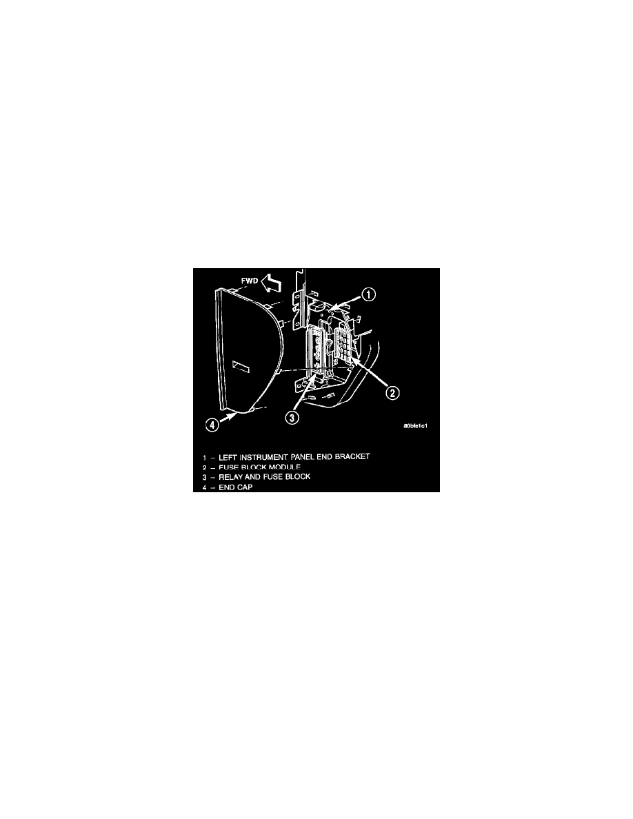
An electrical fuseblock module is concealed behind the driver side instrument panel end cap, just rearward of the relay and fuse block. The
fuseblock module serves to distribute electrical current to many of the accessory systems in the vehicle. The fuseblock module houses up to twenty
blade-type mini fuses, up to two blade-type automatic resetting circuit breakers and an International Standards Organization (ISO) relay.
Additional provisions are available in the fuseblock module for a second ISO relay and an ignition lamp time delay relay; however, these
provisions are not used in this vehicle application.
The molded plastic fuseblock module housing has an integral mounting bracket that is secured with two screws to the left instrument panel end
bracket. The driver side instrument panel end cap also serves as a snap-fit fuse access panel that can be removed for service of the fuseblock
module and the relay and fuse block. A finger recess is molded into the end cap for easy removal. A fuse layout map is molded onto the back side
of the end cap to ensure proper fuse identification.
The fuseblock module is integral to the instrument panel wire harness. If any internal circuit or the fuseblock module housing is faulty or damaged,
the entire fuseblock module and instrument panel wire harness unit must be replaced.
All of the circuits entering and leaving the fuse- block module do so through the instrument panel wire harness. Internal connection of all of the
fuse- block module circuits is accomplished by an intricate combination of hard wiring and bus bars.
RELAY AND FUSE BLOCK