
RAM 3500 Truck 2WD L6-5.9L DSL Turbo (2008)
NOTE: Extreme pressure lubrication must be used on the threaded portions of the tool. This will increase the longevity of the tool and insure
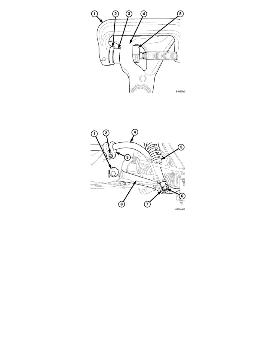
proper operation during the removal and installation process.
1. Install the new shock bushing (3) into the lower control arm (4) using tools C-4212-F (Press) (1), 9653-3 (driver) (2), 9773 (Receiver) (5) will
automatically set the depth of the bushing in the control arm.
2. Install the lower part of the shock (5) into the lower control arm shock bushing (7).
3. Install and position bolt (6) so head of bolt is facing rearward of vehicle and hand start nut. Tighten the bolt (6) & nut to 81 Nm (60 ft. lbs.).
4. Install the upper ball joint to the knuckle and install the retaining nut.
5. Install and tighten the axle hub nut.
6. Install the stabilizer link lower nut.
7. Reconnect the wheel speed sensor wiring to the knuckle and upper control arm.
8. Install the rotor See: Brakes and Traction Control/Disc Brake System/Brake Rotor/Disc/Service and Repair/Removal and Replacement/Brake
Rotor - Installation .
9. Install the caliper adapter with the caliper See: Brakes and Traction Control/Disc Brake System/Brake Caliper/Service and Repair/Removal and
Replacement/Disc Brake Caliper Adapter - Installation .
10. Remove the support from the lower control arm outboard end.
11. Install the tire and wheel assembly See: Wheels and Tires/Service and Repair/Removal and Replacement .
12. Remove the support and lower the vehicle.