
RAM 3500 Truck 2WD L6-5.9L DSL Turbo VIN 7 (2002)
Remote Control: Testing and Inspection
For complete circuit diagrams, refer to the appropriate wiring information. The wiring information includes wiring diagrams, proper wire and connector
repair procedures, details of wire harness routing and retention, connector pin-out information and location views for the various wire harness
connectors, splices and grounds.
WARNING: ON VEHICLES EQUIPPED WITH AIRBAGS, REFER TO ELECTRICAL, RESTRAINTS BEFORE ATTEMPTING ANY
STEERING WHEEL, STEERING COLUMN, OR INSTRUMENT PANEL COMPONENT DIAGNOSIS OR SERVICE. FAILURE TO TAKE
THE PROPER PRECAUTIONS COULD RESULT IN ACCIDENTAL AIRBAG DEPLOYMENT AND POSSIBLE PERSONAL INJURY.
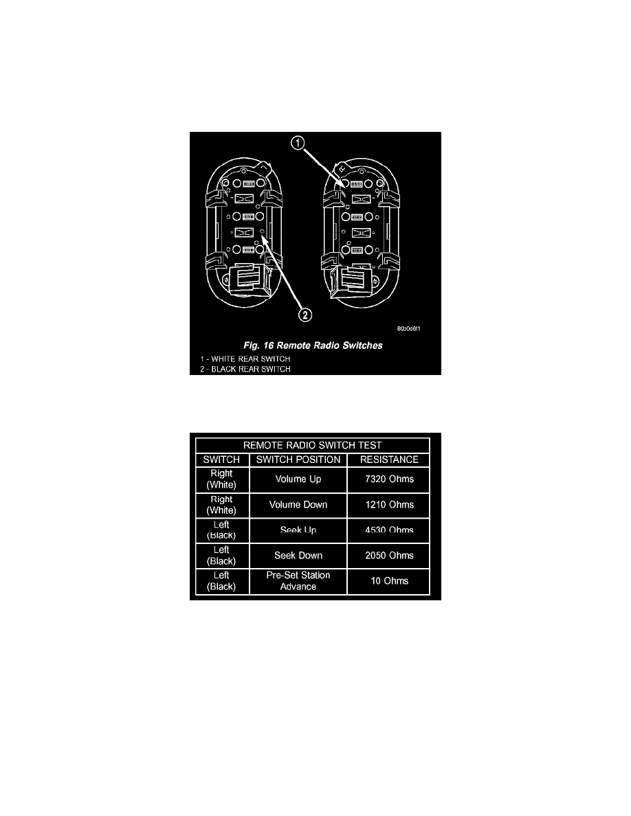
Fig. 16 Remote Radio Switches
1. Remove the remote radio switch(es) from the steering wheel.
Remote Radio Switch Test
2. Use an ohmmeter to check the switch resistances as shown in the Remote Radio Switch Test chart. If the remote radio switch resistances check
OK, go to Step 3. If not OK, replace the faulty switch.
3. Check for continuity between the ground circuit cavity of the remote radio switch wire harness connector and a good ground. There should be
continuity If OK, go to Step 4. If not OK, repair the open ground circuit to ground as required.
4. Disconnect the 18-way wire harness connector from the Central Timer Module (CTM). Check for continuity between the radio control mux circuit
cavity of the remote radio switch wire harness connector and a good ground. There should be no continuity. If OK, go to Step 5. If not OK, repair
the shorted radio control mux circuit as required.
5. Check for continuity between the radio control mux circuit cavities of the remote radio switch wire harness connector and the 18-way CTM wire
harness connector. There should be continuity If OK, refer to the proper Diagnostic Procedures to test the CTM and the Chrysler Collision
Detection (CCD) data bus. If not OK, repair the open radio control mux circuit as required.