
RAM 3500 Truck 2WD L6-5.9L DSL Turbo VIN 7 (2002)
8. Remove the nut that secures the eyelet of the battery positive cable PDC take out to the forward B(+) terminal stud in the PDC and remove the
eyelet from the stud.
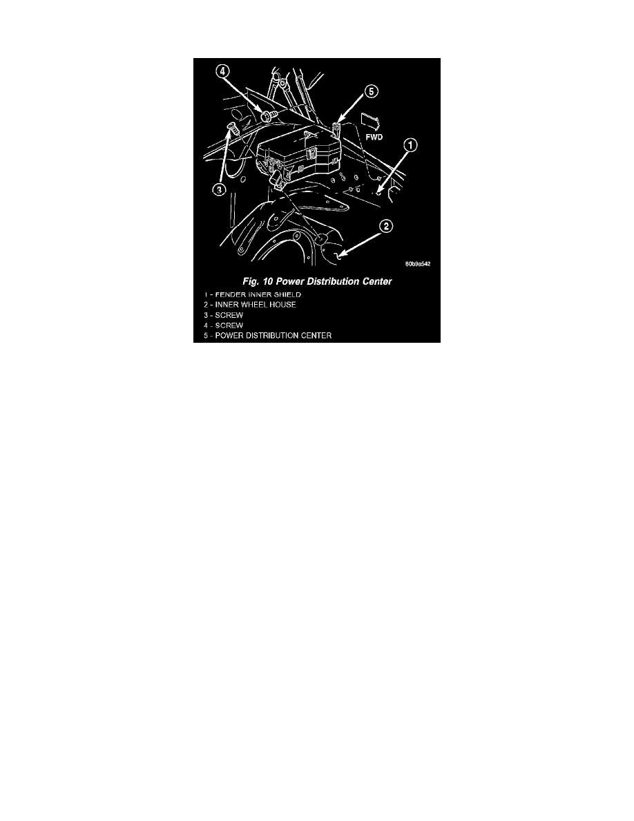
Fig. 10 Power Distribution Center
9. Remove the screw that secures the PDC housing to the left front fender wheel housing (Fig. 10).
10. Remove the two screws that secure the PDC housing to the left front fender inner shield.
11. Remove the PDC and the headlamp and dash wire harness from the engine compartment as a unit.
INSTALLATION
The Power Distribution Center (PDC) is serviced as a unit with the headlamp and dash wire harness. If any internal circuit of the PDC or the PDC
housing is faulty or damaged, the entire PDC and headlamp and dash wire harness unit must be replaced.
NOTE: If the PDC is being replaced with a new unit, be certain to transfer each of the blade-type fuses, cartridge fuses and relays from the faulty PDC
to the proper cavities of the replacement PDC. Refer to Power Distribution in the index for the location of complete PDC circuit diagrams and
cavity assignments.
1. Position the PDC and the headlamp and dash wire harness unit in the engine compartment.
2. Install and tighten the two screws that secure the PDC housing to the left front fender inner shield. Tighten the screws to 8.4 Nm (75 in. lbs.).
3. Install and tighten the screw that secures the PDC housing to the left front fender wheel housing. Tighten the screw to 2.2 Nm (20 in. lbs.).
4. Install the eyelet of the battery positive cable PDC take out onto the forward B(+) terminal stud in the PDC.
5. Install and tighten the nut that secures the eyelet of the battery positive cable PDC take out to the forward B(+) terminal stud in the PDC. Tighten
the nut to 8.4 Nm (75 in. lbs.).
6. Install the eyelet of the battery negative cable generator output take out onto the rearward B(+) terminal stud in the PDC.
7. Install and tighten the nut that secures the eyelet of the battery negative cable generator output take out to the rearward B(+) terminal stud in the
PDC. Tighten the nut to 75 in. lbs.
8. Reconnect the engine wire harness in-line connector to the PDC.
9. Install and tighten the screw that secures the engine wire harness in-line connector to the PDC. Tighten the screw until a distinct audible click is
heard.
10. Install and latch the cover onto the PDC.
11. Engage each of the retainers that secure the headlamp and dash wire harness to the vehicle body and chassis components. Refer to Connector
Locations in Wiring for the location of more information on the headlamp and dash wire harness retainer locations.
12. Install all of the fasteners that secure each of the headlamp and dash wire harness ground eyelets to the vehicle body and chassis components.
Refer to Connector Locations in Wiring for the location of more information on the ground eyelet locations.
13. Reconnect each of the headlamp and dash wire harness connectors. Refer to Connector Locations in Wiring for the location of more information
on the headlamp and dash wire harness connector locations.
14. Reconnect the battery negative cable.