
RAM 3500 Truck 2WD L6-5.9L DSL Turbo VIN 7 (2002)
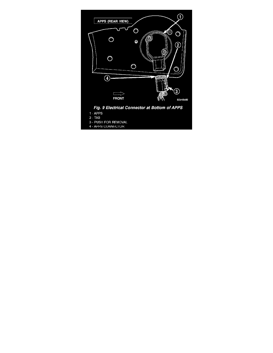
Fig.9 Electrical Connector At Bottom Of APPS
10. Remove 6 mounting bolts (Fig. 8) and partially remove APPS assembly from engine. After assembly is partially removed, disconnect electrical
connector from bottom of sensor by pushing on connector tab (Fig. 9).
11. Remove APPS assembly from engine.
INSTALLATION
The APPS is serviced (replaced) as one assembly including the lever, brackets and sensor. The APPS is calibrated to its mounting bracket. The APPS
assembly is located at left-front of engine below plastic cable/lever/linkage cover (Fig. 6)
1. Snap electrical connector into bottom of sensor.
2. Position APPS assembly to engine and install 6 bolts. Tighten bolts to 12 Nm (105 in. lbs.) torque.
3. Connect wiring harness clip (Fig. 8) at bottom of bracket.
4. If equipped with an automatic transmission.
5. Install speed control cable into mounting bracket. Be sure pinch tabs (Fig. 7) have secured cable.
6. Install throttle cable into mounting bracket. Be sure pinch tabs (Fig. 7) have secured cable.
7. Connect throttle cable at lever (snaps on).
8. Connect speed control cable to lever by pushing cable connector rearward onto lever pin while holding lever forward.
9. Install cable cover.
10. Connect both negative battery cables to both batteries.
11. ECM Calibration: Turn key to ON position. Without starting engine, slowly press throttle pedal to floor and then slowly release. This step must
be done (one time) to ensure accelerator pedal position sensor calibration has been learned by ECM. If not done, possible DTC's may be set.
12. Use DRB scan tool to erase any DTC's from ECM/PCM.