
RAM 3500 Truck 2WD L6-5.9L DSL Turbo VIN 7 (2002)
Power Door Lock Switch: Testing and Inspection
The Light-Emitting Diode (LED) illumination lamps for all of the power window and lock switch and bezel unit switch paddles receive battery current
through the power window circuit breaker in the Junction Block (JB). If all of the LEDs are inoperative in either or both power window and lock switch
and bezel units, be certain to diagnose the power window system before replacing the switch unit. (Refer toPOWER WINDOWS - DIAGNOSIS AND
TESTING See: Windows and Glass/Windows). If only one LED in a power window and lock switch and bezel unit is inoperative, replace the faulty
switch and bezel unit. Refer to the appropriate wiring information. The wiring information includes wiring diagrams, proper wire and connector repair
procedures, details of wire harness routing and retention, connector pin-out information and location views for the various wire harness connectors,
splices and grounds.
1. Check the fused B(+) fuse (Fuse 13 - 10 ampere) in the Junction Block (JB). If OK, go to Step 2. If not OK, repair the shorted circuit or
component as required and replace the faulty fuse.
2. Check for battery voltage at the fused B(+) fuse (Fuse 13 - 10 ampere) in the JB. If OK, go to Step 3. If not OK, repair the open fused B(+) circuit
between the JB and the Power Distribution Center (PDC) as required.
3. Disconnect and isolate the battery negative cable. Remove the power window and lock switch and bezel unit from the door trim panel. Disconnect
the door wire harness connector for the power window and lock switch unit from the switch connector receptacle.
4. Reconnect the battery negative cable. Check for battery voltage at the fused B(+) circuit cavity of the door wire harness connector for the power
window and lock switch unit. If OK, go to Step 5. If not OK, repair the open fused B(+) circuit between the power window and lock switch unit
and the JB as required.
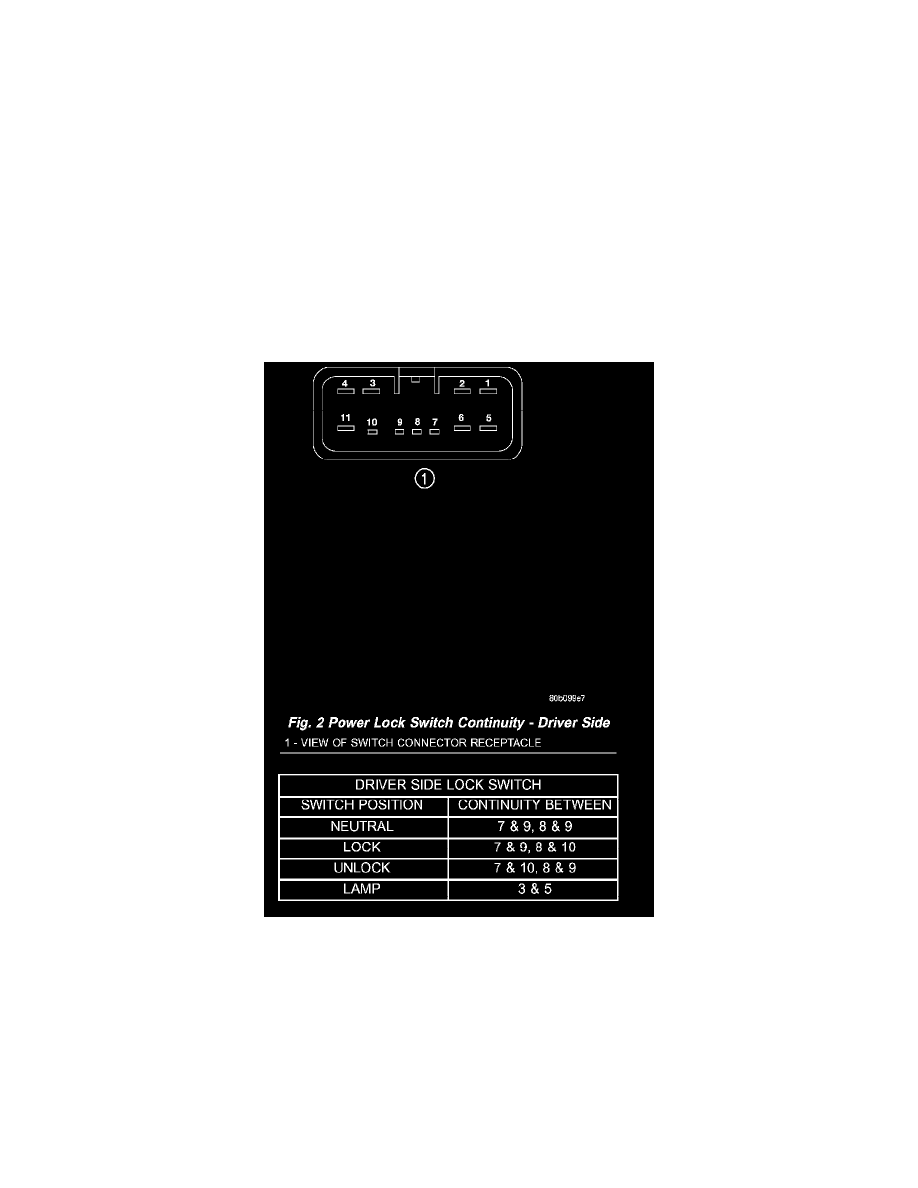
Fig. 2 Power Lock Switch Continuity - Driver Side