
RAM 3500 Truck 2WD L6-5.9L DSL Turbo VIN C (2003)
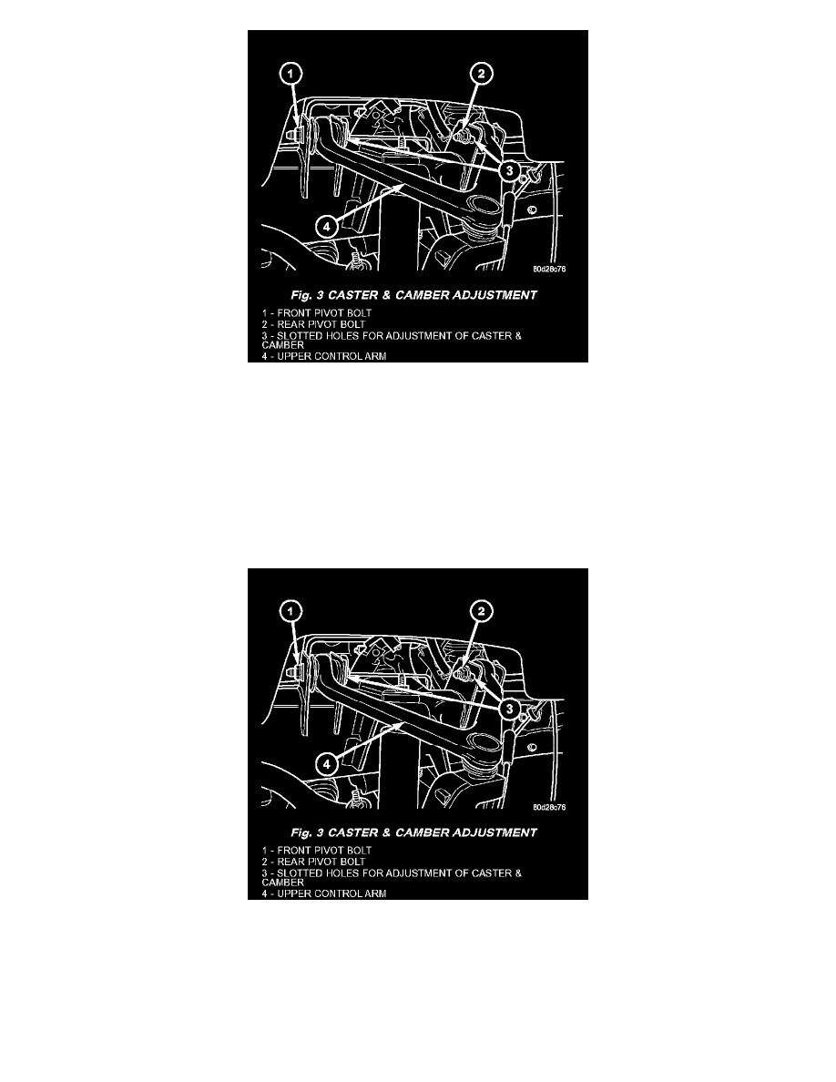
Fig. 3
Camber and caster angle adjustments involve changing the position of the upper control arm in conjunction with the slotted holes in the frame
brackets, Install special tool 8876 between the top of the upper control arm bracket and the upper control arm (on 1500 series 4X2 & 4X4). Install
special tool 8876 between the bottom of the upper control arm bracket pressing the tool against the frame and the upper control arm (on 2500/3500
series 4X2) in order to move the upper control arm outwards for proper adjustment with the vehicle at normal ride height.
Camber, Caster and Toe Adjustment
STANDARD PROCEDURE - CAMBER,CASTER AND TOE ADJUSTMENT
NOTE: 4X4 (LD) SUSPENSION HEIGHT MEASUREMENT MUST BE PERFORMED BEFORE AN ALIGNMENT.
Fig. 3
Camber and caster angle adjustments involve changing the position of the upper control arm with the slots in the frame brackets using special tool
8876 to move the upper control arm outwards for proper adjustment.
NOTE: When the upper control arm pivot bolts are loosened the upper control arm will normally go inwards toward the frame automatically with the
weight of the vehicle.