
RAM 3500 Truck 2WD L6-5.9L DSL Turbo VIN C (2003)
CASTER
Moving the front or rear position of the upper control arm in or out, will change the caster angle and camber angle significantly. To maintain the
camber angle while adjusting caster, move one pivot bolt of the upper control arm in or out. Then move the other pivot bolt of the upper control arm in
the opposite direction. Install special tool 8876 between the top of the upper control arm bracket and the upper control arm (on 1500 series 4X2 &
4X4). Install special tool 8876 between the bottom of the upper control arm bracket pressing the tool against the frame and the upper control arm (on
2500/3500 series 4X2) in order to move the upper control arm outwards for proper adjustment with the vehicle at normal ride height.
To increase positive caster angle, move the rear position of the upper control arm inward (toward the engine). Move the front of the upper control arm
outward (away from the engine) slightly until the original camber angle is obtained using special tool 8876 to move the upper control arm for proper
adjustment.
CAMBER
Move both pivot bolts of the upper control arm together in or out. This will change the camber angle significantly and little effect on the caster angle
using special tool 8876 to move the upper control arm for proper adjustment.
After adjustment is made tighten the upper control arm nuts to proper torque specification.
TOE ADJUSTMENT
The wheel toe position adjustment is the final adjustment.
1. Start the engine and turn wheels both ways before straightening the wheels. Secure the steering wheel with the front wheels in the straight-ahead
position.
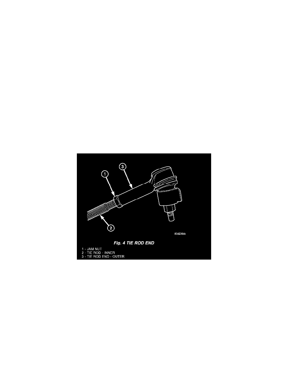
2. Loosen the tie rod jam nuts.
NOTE: Each front wheel should be adjusted for one-half of the total toe position specification. This will ensure the steering wheel will be
centered when the wheels are positioned straight-ahead.
Fig. 4
3. Adjust the wheel toe position by turning the inner tie rod as necessary.
4. Tighten the tie rod jam nut to 75 Nm (55 ft. lbs.).
5. Verify the specifications
6. Turn off engine.
Toe Adjustment
STANDARD PROCEDURE - TOE ADJUSTMENT
4X4 SUSPENSION HEIGHT MEASUREMENT MUST BE PERFORMED BEFORE AN ALIGNMENT.
The wheel toe position adjustment is the final adjustment.
1. Start the engine and turn wheels both ways before straightening the wheels. Secure the steering wheel with the front wheels in the straight-ahead
position.
2. Loosen the tie rod jam nuts.
NOTE: Each front wheel should be adjusted for one-half of the total toe position specification. This will ensure the steering wheel will be
centered when the wheels are positioned straight-ahead.