
RAM 3500 Truck 2WD L6-6.7L DSL Turbo (2010)
Valve: Removal and Replacement
Intake and Exhaust Valves - Removal
REMOVAL
1. Disconnect both negative battery cables.
2. Remove the cylinder head cover See: Valve Cover/Service and Repair/Removal and Replacement/Cylinder Head Cover(s) - Removal.
3. Disconnect the injector harness connectors at cylinder head cover gasket. Remove all injector solenoid nuts. Remove cylinder head cover gasket.
4. Remove injector(s) for cylinder(s) to be serviced. See: Powertrain Management/Fuel Delivery and Air Induction/Fuel Injector/Service and
Repair/Fuel Injector - Removal or See: Powertrain Management/Fuel Delivery and Air Induction/Fuel Injector/Service and Repair/Fuel Injector -
Removal
5. Remove the rocker housing.
6. Remove the rocker arms and crossheads from the cylinder(s) to be serviced. Mark each component so they can be installed in their original
position.
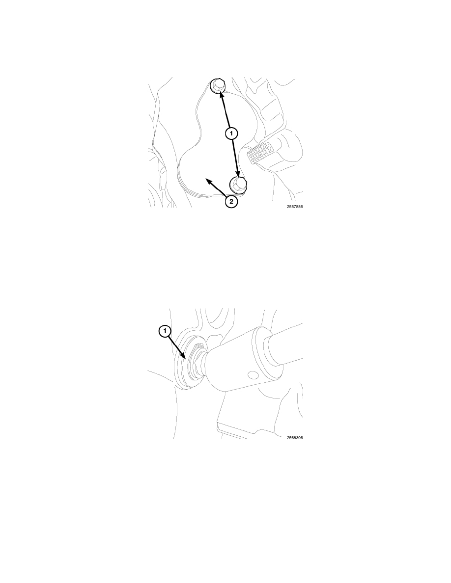
7. Remove bolts (1) and the bell housing access cover (2).
NOTE: At this engine position, cylinders No. 1 and No. 6 can be serviced.
8. Using the barring tool 7471B (1), rotate the engine to position the damper mark in the 12 o'clock position.
9. Remove the accessory drive belt See: Drive Belts, Mounts, Brackets and Accessories/Drive Belt/Service and Repair/Serpentine Accessory Drive
Belt - Removal.
10. With the damper TDC mark in the 12 o'clock position, add a paint mark anywhere on the gear housing cover next to the crankshaft damper. Place
another mark on the vibration damper in alignment with the mark you just made on the cover.
11. Divide the crankshaft damper into three equally sized segments as follows:
a. Using a tape measure, measure the circumference of the crankshaft damper and divide the measurement by three (3).
b. Measure that distance in a counterclockwise direction from the first balancer mark and place another mark on the balancer.
c. From the second damper mark, again measure in a counterclockwise direction and place a mark on the damper at the same distance you
measured when placing the second damper mark. The damper should now be marked in three equally spaced locations and the damper TDC
mark should be in the 12 o'clock position.
d. Remove injectors, fuel lines, and high pressure connectors for every cylinder that requires repair.