
RAM 3500 Truck 2WD L6-6.7L DSL Turbo (2010)
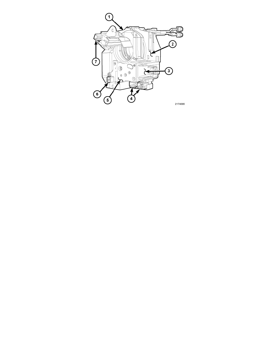
The lower surface of the clockspring case (1) facing toward the instrument panel includes two receptacles on the left for mounting the multi-function
switch (2) and the optional adjustable pedal switch (3). There are two integral connector receptacles (4) on the left lower corner of the clockspring case.
Clocksprings with a SAS (5) also have a dedicated connector (6) near the right lower corner of that unit. Vehicles equipped with the optional heated
steering wheel also have a dedicated connector (7) to the internal slip rings on the upper right corner of the clockspring case.
Within the plastic case and wound around the rotor spool is a long ribbon-like tape that consists of several thin copper wire leads sandwiched between
two thin plastic membranes. The outer end of the tape terminates at the connector receptacles that face the instrument panel, while the inner end of the
tape terminates at the driver airbag squib pigtail wires and connector receptacle on the hub of the clockspring rotor that face the steering wheel.
The clockspring cannot be repaired. If damaged, ineffective or if the driver airbag has been deployed, the clockspring must be replaced.