
RAM 3500 Truck 2WD L6-6.7L DSL Turbo (2010)
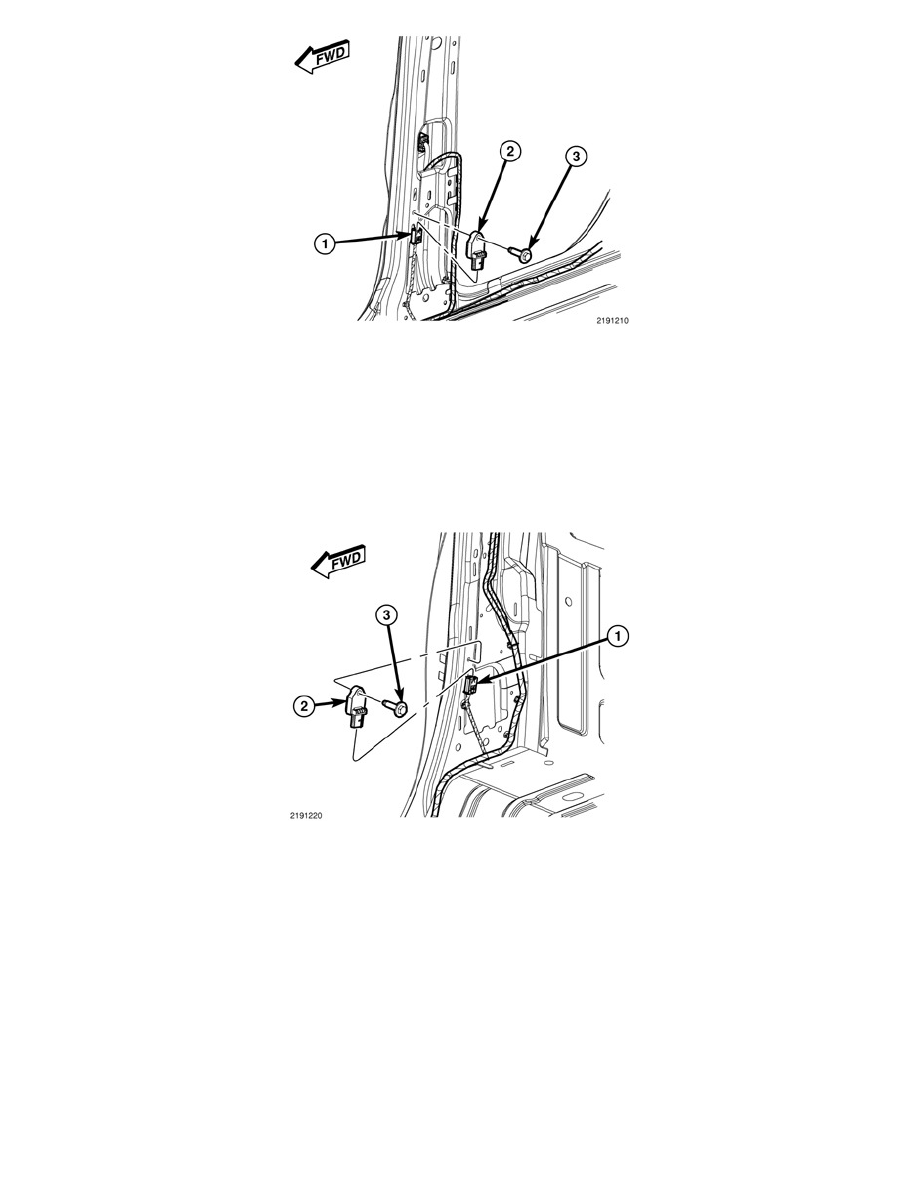
1. Position the side impact sensor (2) to the inside of B-pillar. Be certain that the anti-rotation pin on the back of the sensor is engaged in the
clearance hole of the B-pillar.
2. Install and tighten the screw (3) that secures the sensor to the inner B-pillar. Tighten the screw to 9 Nm (80 in. lbs.).
3. Reconnect the body wire harness connector (1) to the sensor connector receptacle.
4. Reinstall the trim onto the inside of the lower B-pillar. See: Body and Frame/Interior Moulding / Trim/Trim Panel/Service and Repair/Pillar
Trim/B-Pillar Trim Panel - Installation.
5. Do not reconnect the battery negative cable at this time. The Supplemental Restraint System (SRS) verification test procedure should be performed
following service of any SRS component. See: Service and Repair.
C-PILLAR
1. Position the side impact sensor (2) to the inside of C-pillar. Be certain that the anti-rotation pin on the back of the sensor is engaged in the
clearance hole of the C-pillar.
2. Install and tighten the screw (3) that secures the sensor to the inner B-pillar. Tighten the screw to 9 Nm (80 in. lbs.).
3. Reconnect the body wire harness connector (1) to the sensor connector receptacle.
4. Reinstall the trim onto the inside of the lower C-pillar. See: Body and Frame/Interior Moulding / Trim/Trim Panel/Service and Repair/Pillar
Trim/C-Pillar Trim Panel - Installation.
5. Do not reconnect the battery negative cable at this time. The Supplemental Restraint System (SRS) verification test procedure should be performed
following service of any SRS component. See: Service and Repair.