
RAM 3500 Truck 2WD V10-8.0L VIN W HDC (2000)
Turn Signal Flasher: Description and Operation
The combination flasher is a smart relay that functions as both the turn signal system and the hazard warning system flasher. The combination flasher
contains active electronic Integrated Circuitry (IC) elements. This flasher is designed to handle the current flow requirements of the factory-installed
lighting. If supplemental lighting is added to the turn signal lamp circuits, such as when towing a trailer with lights, the combination flasher will
automatically try to compensate to keep the flash rate the same.
While the combination flasher has a International Standards Organization (ISO)-type relay terminal configuration or footprint, the internal circuitry is
much different. The combination flasher does not use standard ISO-relay inputs or provide ISO-relay type outputs or functions. The combination flasher
should never be substituted for an ISO-relay or replaced with an ISO-relay, or else component and vehicle damage may occur.
Because of the active electronic elements within the combination flasher, it cannot be tested with conventional automotive electrical test equipment. If
the combination flasher is believed to be faulty, test the turn signal system and hazard warning system circuits as described in this. Then replace the
combination flasher with a known good unit to confirm system operation.
The combination flasher has five blade-type terminals intended for the following inputs and outputs:fused B(+), fused ignition switch output, ground,
turn signal circuit, and hazard warning circuit. Constant battery voltage and ground are supplied to the flasher so that it can perform the hazard warning
function, and ignition switched battery voltage is supplied for the turn signal function.
The combination flasher is located in the junction block behind the fuse access panel on the left end of the instrument panel. The combination flasher
cannot be repaired or adjusted and, if faulty or damaged, it must be replaced.
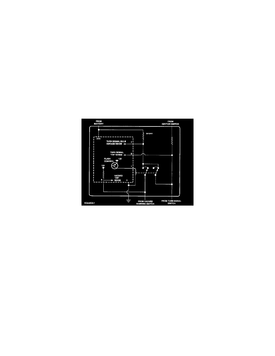
Combination Flasher - Typical
The IC within the combination flasher contains the logic that controls the flasher operation and the flash rate. Pin 6 of the IC receives a sense voltage
from the hazard warning circuit of the multi-function switch. When the hazard warning switch is turned on, the "hazard on sense" voltage will become
low due to the circuit being grounded through the turn signal bulbs. This low voltage sense signals the IC to energize the flash control
Positive-Negative-Positive (PNP) transistor at a pre-calibrated flash rate or frequency. Each time the PNP transistor energizes the hazard warning circuit,
the pin 6 "hazard on sense" voltage will become high and the IC signals the PNP transistor to de-energize the circuit. This cycling will continue until the
hazard warning switch is turned off.
Likewise, pin 8 of the IC receives a sense voltage from the turn signal circuits of the multi-function switch. When the left or right turn signal switch is
turned on, the "turn signal on sense" voltage will become low due to the circuit being grounded through the turn signal bulbs. This low voltage sense
signals the IC to energize the flash control PNP transistor at a pre-calibrated flash rate or frequency Each time the PNP transistor energizes the turn
signal circuit, the pin 8 "turn signal on sense" voltage will become high and the IC signals the PNP transistor to de-energize the circuit. This cycling will
continue until the right or left turn signal switch is turned off.
A special design feature of the combination flasher allows it to "sense" that a turn signal circuit or bulb is not operating, and provide the driver an
indication of the condition by flashing the remaining bulbs in the affected circuit at a higher rate (120 flashes-per-minute or higher). Conventional
flashers either continue flashing at their typical rate (heavy-duty type), or discontinue flashing the affected circuit entirely (standard-duty type). During
turn signal operation, the combination flasher IC compares normal battery voltage input on pin 2 with the shunt resistor voltage input on pin 7. If the IC
"senses" that the voltage difference between pin 2 and pin 7 is different than the pre-calibrated value of the IC, it will increase the rate at which it signals
the PNP transistor to energize the pin 1 output. Thus, the inoperative half (left or right side) of the turn signal circuit will flash faster.