
RAM 3500 Truck 2WD V10-8.0L VIN W HDC (2000)
Control Arm: Service and Repair
Front Suspension
Lower Suspension Arm
REMOVAL
1. Raise and support vehicle.
2. Remove tire and wheel assembly.
3. Remove brake caliper assembly and rotor refer to Brakes and Traction Control, Brakes, Disc Brake System for information.
4. Remove cotter pin and nut from the tie rod. Remove the tie rod end from the steering knuckle with Puller C-3894-A.
5. Remove stabilizer bar link from lower suspension arm.
6. Support lower suspension arm outboard end with jack. Place jack under arm in front of shock mount.
7. Remove cotter pin and nut from lower ball joint. Separate ball joint with Remover C-4150A.
8. Remove lower shock bolt from suspension arm.
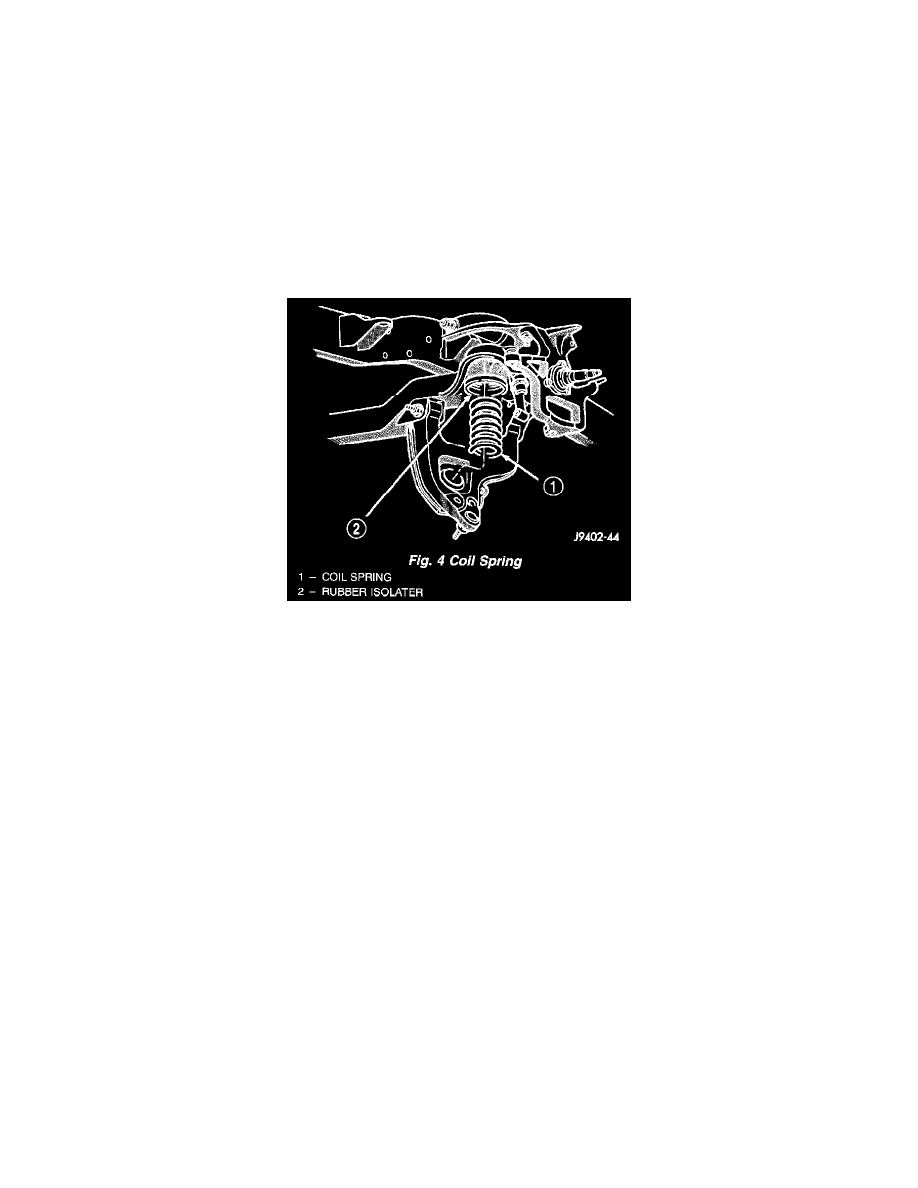
9. Lower jack and suspension arm until spring tension is relieved. Remove spring and rubber isolator.
10. Remove bolts mounting suspension arm to crossmember and remove arm.
INSTALLATION
1. Position suspension arm on crossmember and install bolts and nuts snug.
2. Install rubber isolator on top of spring. Position spring into upper spring seat.
3. Raise lower suspension arm with jack and position spring into the lower suspension arm mount.
4. Install lower shock bolt and tighten to 142 Nm (105 ft. lbs.).
5. Install steering knuckle on lower ball joint. Install lower ball joint nut and tighten to:
-
LD: 129 Nm (95 ft. lbs.)
-
HD: 136 Nm (110 ft. lbs.)
5. Install lower ball joint cotter pin.
6. Install stabilizer bar link on lower suspension arm. Install grommet, retainer and nut and tighten to 37 Nm (27 ft. lbs.).
7. Install the tie rod end on the steering knuckle and tighten nut to 108 Nm (80 ft. lbs.). Install cotter pin.
8. Install brake rotor and caliper assembly, refer to Brakes and Traction Control, Brakes, Disc Brake System for information.
9. Install tire and wheel assembly.
10. Remove support and lower vehicle.
11. Tighten suspension arm crossmember nuts to 169 Nm (125 ft. lbs.).
Upper Suspension Arm
See TSB NHTSA00V307000 (Recall 00V307000) Oct. 2000
REMOVAL
1. Raise and support vehicle.
2. Remove tire and wheel assembly.
3. Support lower suspension arm at outboard end with jack stand.
4. Remove upper ball joint cotter pin and nut.
5. Separate ball joint from knuckle with remover MB-990635.